
Wall structure of house building and construction method

A technology for building walls and houses, applied in building components, building structures, buildings, etc., can solve the problems of troublesome installation, low space utilization, and inability to place blocks, so as to achieve convenient installation of blocks and improve space utilization. Effect

Active Publication Date: 2020-06-05
宜宾戊辰建设有限公司
View PDF17 Cites 0 Cited by
  • Summary
  • Abstract
  • Description
  • Claims
  • Application Information

AI Technical Summary

Problems solved by technology

[0004] However, the above-mentioned invention has one disadvantage in that the first connecting plate and the second connecting plate are exposed to the outside world, which not only affects the appearance, but also makes it impossible to place blocks in the area above the first connecting plate and the second connecting plate, resulting in a high space utilization rate. Low; and mortar needs to be filled between adjacent blocks, which is very troublesome to install

Method used


Image

  • Wall structure of house building and construction method
  • Wall structure of house building and construction method
  • Wall structure of house building and construction method

Examples


Embodiment 1

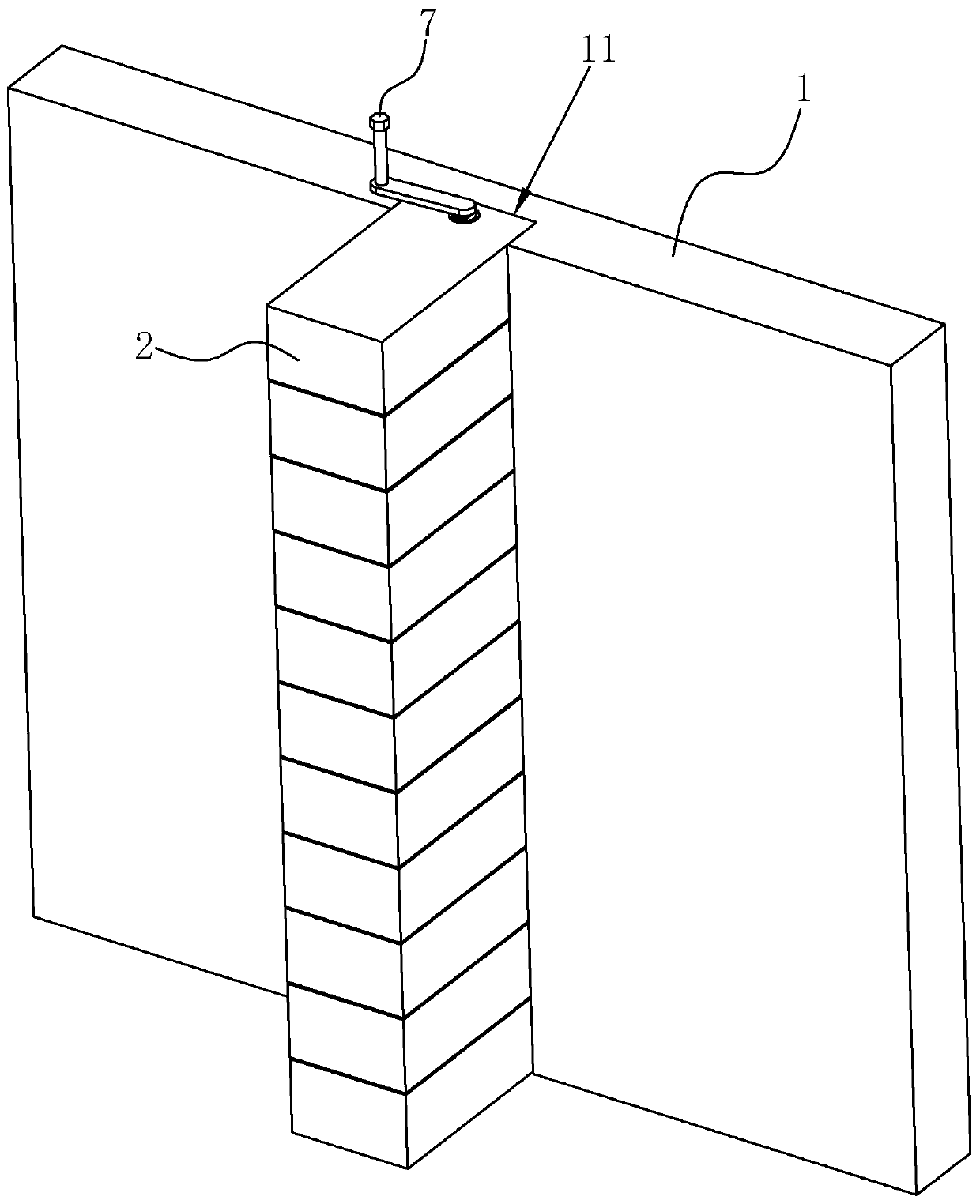
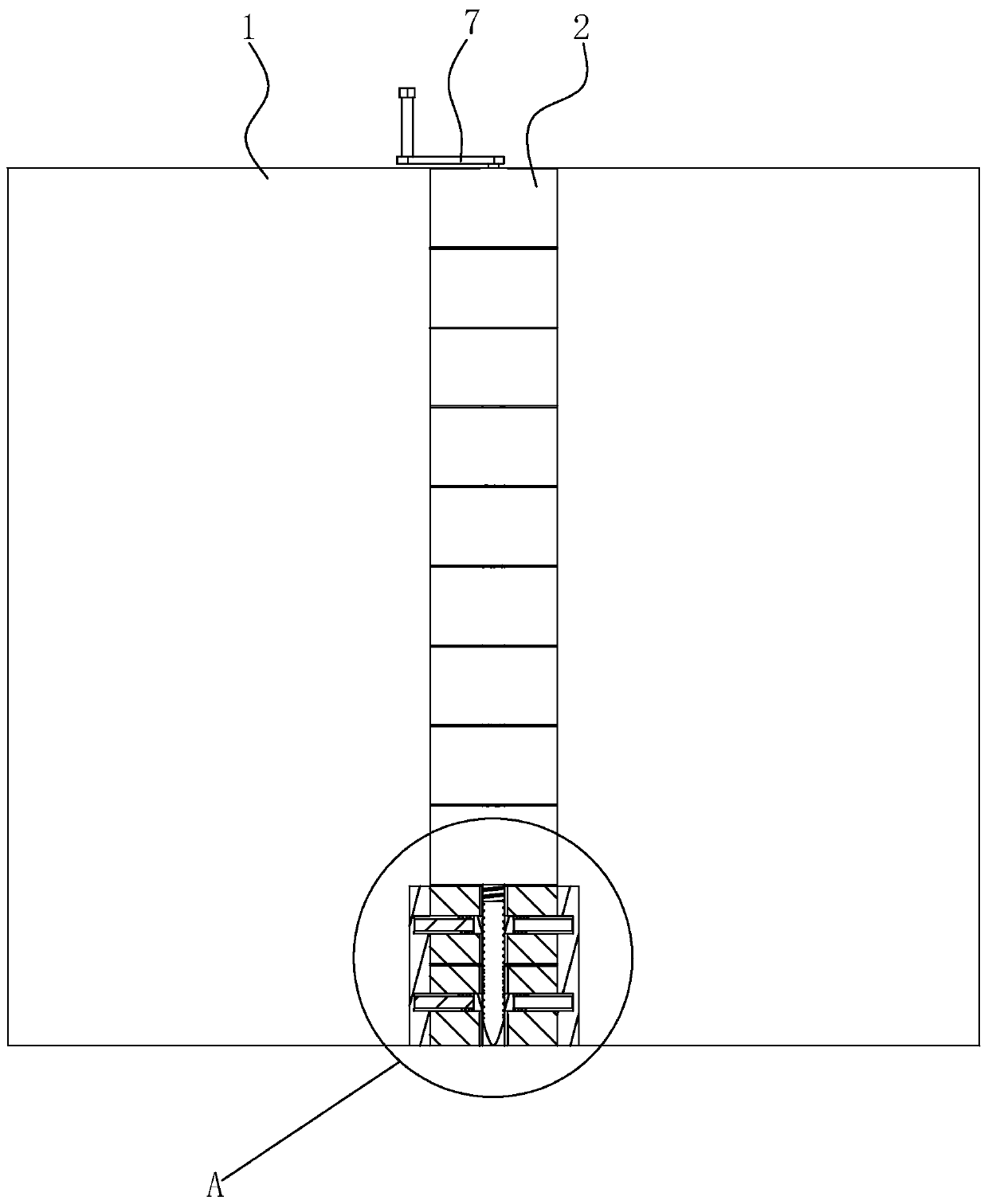
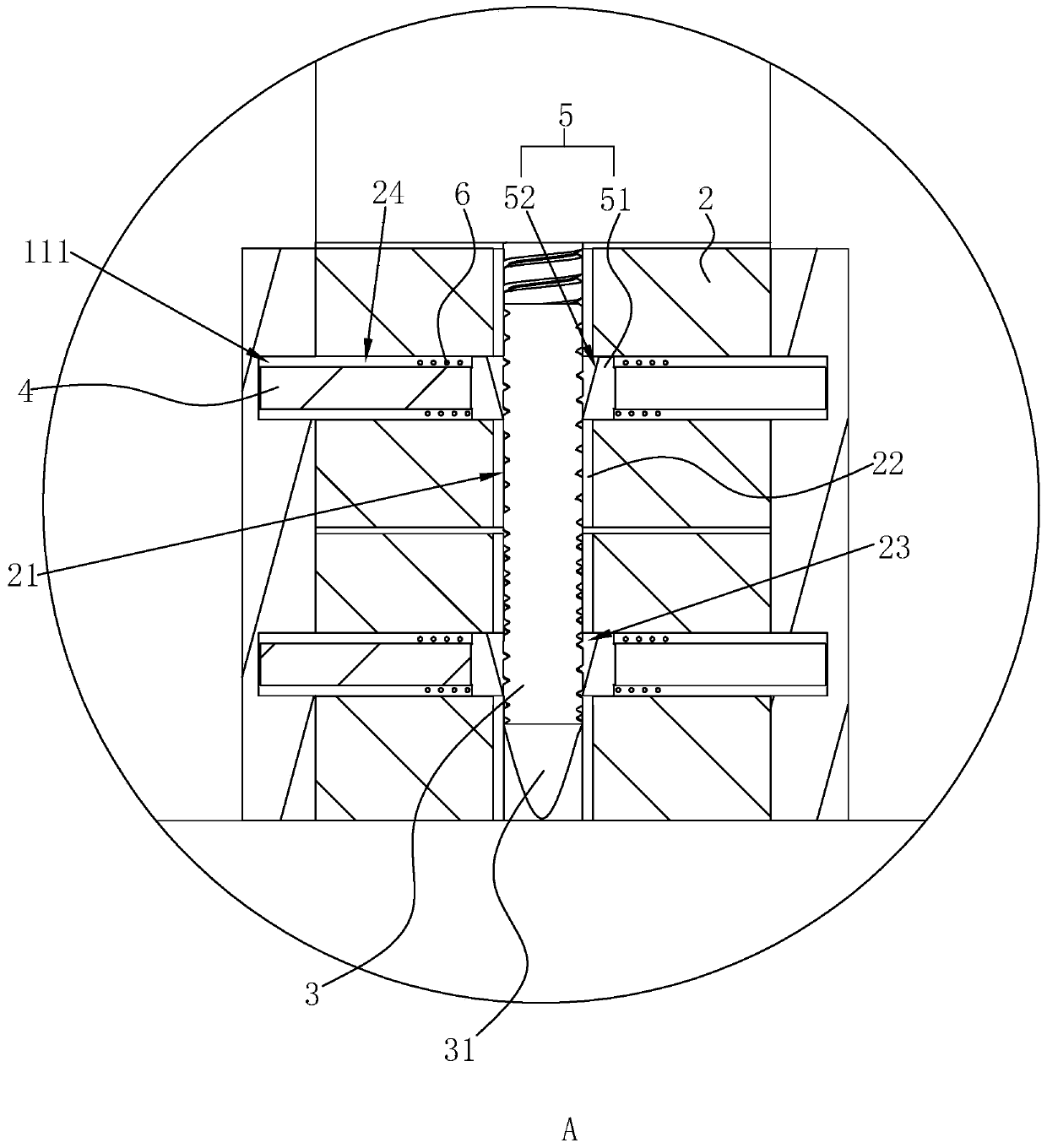
[0042] Example 1: refer to figure 1 , Image 6 , is a building wall structure disclosed in the present invention, comprising a concrete wall 1 and a masonry wall, the masonry wall is formed by stacking a plurality of blocks 2, and the concrete wall 1 is along the concrete wall 1 There is a vertical slot 11 in the height direction of the wall, the vertical slot 11 is used to accommodate the block 2, and the length of the vertical slot 11 is the same as the height of the concrete wall 1; figure 2 , image 3 , the block 2 is provided with a through hole 21, and the length direction of the through hole 21 is parallel to the thickness direction of the block 2. After a plurality of blocks 2 are stacked, the axis of the through hole 21 on each block 2 is in the same vertical direction. On a straight line, that is, the through holes 21 on the plurality of blocks 2 can form a channel.

[0043] like image 3 As shown, a horizontal hole 24 connected to the through hole 21 is lateral...

Embodiment 2

[0051] Embodiment 2: a construction method of a building wall structure, comprising the following steps:

[0052] Step 1. First stack the blocks 2 vertically and put them into the vertical groove 11 in turn, so that the stacked blocks 2 form a masonry wall and fill the vertical groove 11. At this time, the height of the masonry wall is the same as the vertical groove 11. The lengths of the blocks 2 are the same, and the horizontal holes 24 on the block 2 also correspond to the abutting grooves 111 on the inner wall of the vertical groove 11 respectively;

[0053] Step 2: Insert the connecting rod 3 from the through hole 21 on the topmost block 2, then insert the rectangular insertion rod 71 on the crank handle 7 into the rectangular slot 32, and rotate the connecting rod 3 to make the connecting rod 3 gradually. Screw it into the reinforcement cylinder 22 in the through hole 21, let the connecting rod 3 pass through the stacked blocks 2 successively until it touches the ground...


PUM


Abstract

The invention relates to a wall structure of a house building and a construction method and belongs to the technical field of house buildings. The wall structure comprises a concrete wall and a blockwall. The block wall is formed by piling a plurality of blocks. A vertical slot is formed in the concrete wall in a height direction of the concrete wall, a through hole is formed in the block, the length direction of the through hole is parallel to the thickness direction of the block, transverse holes communicating to the through hole are transversely formed in the block, the length directions of the transverse holes are vertical to the length direction of the through hole, the transverse hole is formed in each side of the through hole, a connecting rod is inserted into the through hole, a plurality of leaning slots facing the transverse holes are formed in the side wall of the vertical slot, leaning rods are slidably inserted into the transverse holes, a leaning part is arranged at theend, close to the through hole, of the leaning rod, and when the rod wall of the connecting rod leans against the leaning part, the end, far away from the leaning part, of the leaning rod is pushed into the leaning slot. The wall structure has the advantages of improving the spatial utilization ratio and being convenient to mount the block.

Description

technical field [0001] The invention relates to the technical field of house construction, in particular to a house construction wall structure and a construction method. Background technique [0002] Traditional house construction wall structures include concrete walls and masonry walls. The part of the concrete wall that is used to connect with the masonry wall is reserved with steel bars or implanted with steel bars, and the steel bars are pressed into the adjacent masonry that constitutes the masonry wall during the process of forming the masonry wall. The gaps between the blocks are then filled with mortar to connect the concrete walls to the masonry walls. However, the mortar at the joint between the concrete wall and the masonry wall is extremely prone to cracking. [0003] Therefore, Chinese Patent Application Publication No. CN108086522A discloses a building wall structure and a construction method. The building wall structure includes concrete walls, masonry wall...

Claims


Application Information

Patent Timeline
Patent Type & Authority Applications(China)
IPC IPC(8): E04B2/00E04B2/02E04B2/06
CPCE04B2/00E04B2/02E04B2/06E04B2002/0295
Inventor 柴御钦
Owner 宜宾戊辰建设有限公司
Learn More