Optical modulator

A light modulator and smooth technology, applied in the field of electro-optics, can solve the problems of inability to apply ultra-high-speed display and imaging, inapplicability, low modulation speed, etc., to achieve the effect of fast acceleration, small mass per unit area, and high-efficiency modulation

Active Publication Date: 2020-06-05
GUIZHOU MINZU UNIV
View PDF15 Cites 0 Cited by
  • Summary
  • Abstract
  • Description
  • Claims
  • Application Information

AI Technical Summary

Problems solved by technology

Mechanical light modulation, such as a chopper, has a very wide modulation wavelength range, and can simultaneously regulate the beams in the ultraviolet to far-infrared bands. However, the modulation speed of traditional mechanic

Method used


Image

  • Optical modulator
  • Optical modulator
  • Optical modulator

Examples


Example Embodiment

[0028] Example 1:

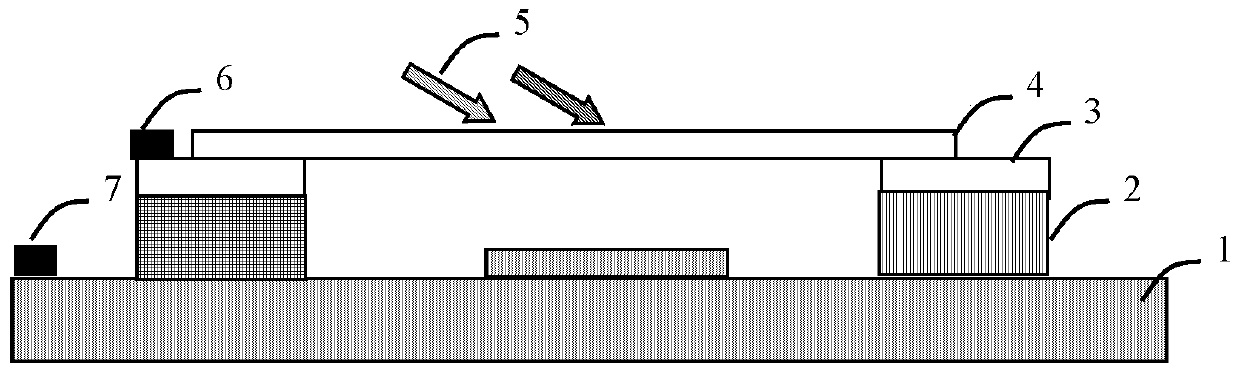
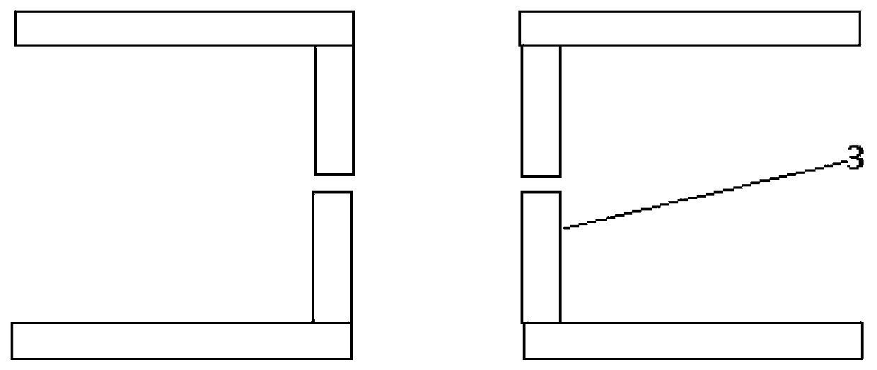
[0029] Such as figure 1 As shown, in this embodiment, a light modulator includes a conductive bottom layer 1. Both ends of the upper surface of the conductive bottom layer 1 are fixedly provided with insulating layers 2, and the upper surfaces of the two insulating layers 2 are both fixed. A lubricating layer 3 is fixed, a two-dimensional material 4 is arranged between the upper surfaces of the two lubricating layers 3, and the lower surfaces at both ends of the two-dimensional material 4 are respectively provided on the upper surfaces of the two lubricating layers 3 Above, the conductive bottom layer 1 is provided with a first electrode 7 and the lubricating layer 3 is provided with a second electrode 6. The positive and negative of the first electrode 7 and the second electrode 6 can be opposite or the same. The dissimilar electrodes are attracted to each other, the distance becomes smaller, the same kind repels, and the distance increases. The middle part o...


PUM


Abstract

The invention discloses an optical modulator. The optical modulator comprises a conductive underlayer, and insulating layers are fixedly arranged at the two ends of the upper surface of the conductiveunderlayer. Lubricating layers are fixedly arranged on the upper surface of the insulating layers, the lower surfaces of the two ends of the two-dimensional material are arranged on the upper surfaces of the lubricating layers, a first electrode is arranged on the conductive underlayer, second electrodes are arranged on the lubricating layers, and the two-dimensional material slides on the lubricating layers. The beneficial effects of the optical modulator are that: the electrostatic force between the two-dimensional material and the base is adjusted by changing the voltage between the two-dimensional material and the conductive underlayer; the two-dimensional material slides on the lubricating layers, the distance between the two-dimensional material and the conductive base is adjusted,so that light regulation and control are achieved, the optical modulator can achieve simultaneous modulation within the ultraviolet-to-infrared spectrum range, the modulation speed is high, the modulation voltage is small, and power consumption is low.

Description

technical field [0001] The invention relates to the field of electro-optic technology, in particular to an optical modulator. Background technique [0002] Optical modulators have a wide range of applications in optical communications and can also be used in radar and laser modulation. Optical modulation includes mechanical modulation, acousto-optic modulation, magneto-optic modulator, electro-optic modulation, and electro-absorption modulation. Among them, electro-optic modulation uses electro-optic effects such as linear electro-optic effect (Pockels effect) to modulate, and its speed is extremely high, but usually it can only work near a specific wavelength, and the modulation wavelength range is narrow. Two-dimensional materials such as graphene have also been used to make electro-optic modulators. It mainly modulates the interband light absorption by modulating the Fermi level of two-dimensional materials. The adjustment frequency is also high. But this modulator ca...

Claims


Application Information

Patent Timeline
IPC IPC(8): G02F1/01
CPCG02F1/0102
Inventor 刘江涛蔡勋明周朝彪范梦慧徐艳丽吴媛媛
Owner GUIZHOU MINZU UNIV
Why Eureka
Try Eureka