Dimming glass and preparation method thereof

A dimming glass and dimming technology, applied in optics, nonlinear optics, instruments, etc., can solve the problem of light leakage in the area where the PS is located

Inactive Publication Date: 2020-06-05
BEIJING BOE OPTOELECTRONCIS TECH CO LTD +1
View PDF4 Cites 5 Cited by
  • Summary
  • Abstract
  • Description
  • Claims
  • Application Information

AI Technical Summary

Problems solved by technology

[0003] The inventors have found that there are at least the following problems in the prior art: the existing dimming glass generally uses a spacer (postspacer, PS) as a support in the box, and since PS is generally a transparent organic substance, in this way, in the dark state, the area where the PS is located There will be light leakage

Method used


Image

  • Dimming glass and preparation method thereof
  • Dimming glass and preparation method thereof
  • Dimming glass and preparation method thereof

Examples


Embodiment 1

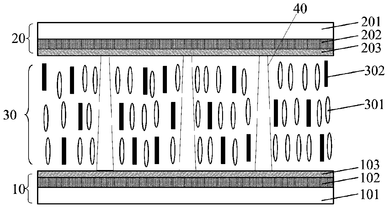
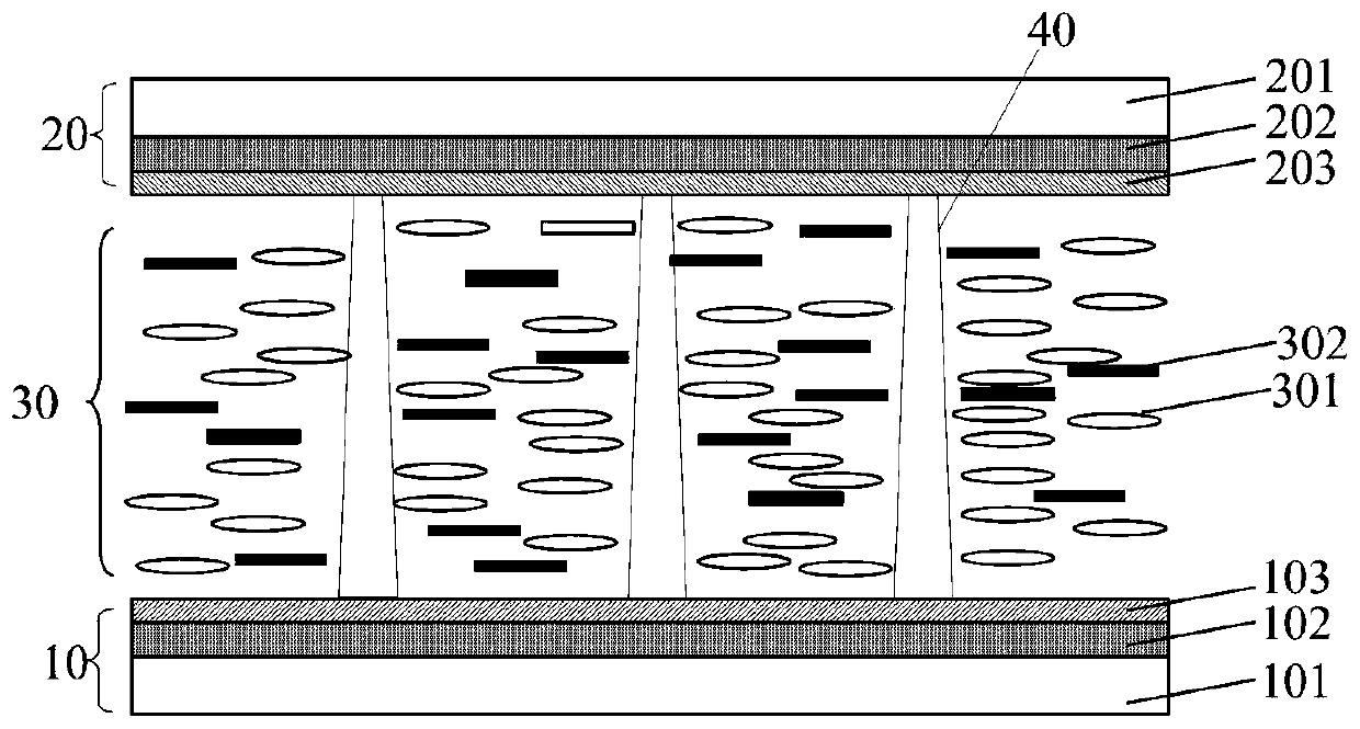
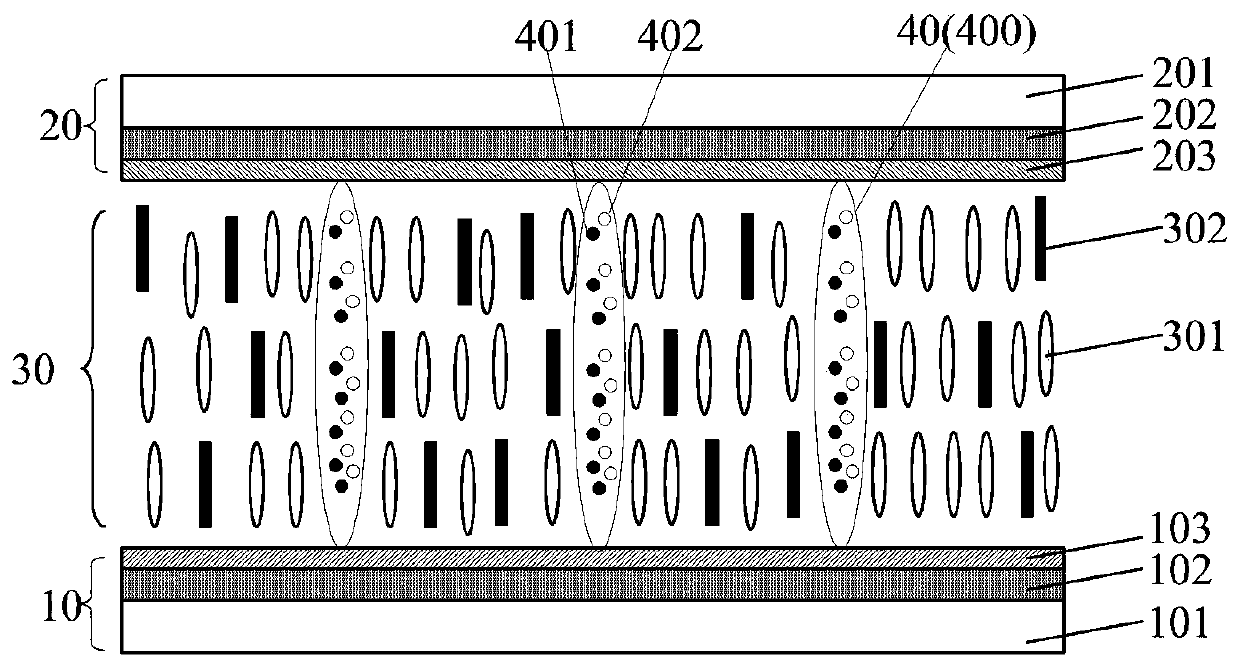
[0038] image 3 and Figure 4 A structural schematic diagram of a dimming glass provided for an embodiment of the present invention, as shown in image 3 and Figure 4 As shown, the dimming glass includes: at least one layer of dimming structure; the dimming structure includes: a first substrate 10 and a second substrate 20 oppositely arranged, and a liquid crystal layer 30 between the first substrate 10 and the second substrate 20 , and maintain the thick spacer 40 of the liquid crystal layer 30 between the first substrate 10 and the second substrate 20; the liquid crystal layer 30 includes: liquid crystal molecules 301; the spacer 40 includes: microcapsules 400; encapsulated in the microcapsules 400 Black charged particles 401 and transparent charged particles 402; wherein, the black charged particles 401 and the transparent charged particles 402 have opposite polarities.

[0039] Such as image 3 As shown, when no voltage is applied between the first substrate 10 and th...

Embodiment 2

[0057] Based on the same inventive concept, an embodiment of the present invention provides a method for preparing a dimming glass, Figure 6 A schematic flow chart of a method for preparing a dimming glass provided in an embodiment of the present invention, as shown in Figure 6 As shown, the preparation method of the dimming glass comprises the following steps:

[0058] S601, encapsulating uniformly mixed black charged particles and transparent charged particles in microcapsules.

[0059] S602. Print the microcapsules on the first substrate through a screen printing process, so that the microcapsules form a preset pattern on the first substrate.

[0060] S603, coating a frame sealant on the first substrate formed with the microcapsules.

[0061] S604, drop the liquid crystal molecules into the region defined by the sealant on the first substrate.

[0062] S605, aligning the second substrate and the first substrate to form a dimming structure.

[0063] The method for prep...


PUM


Abstract

The invention provides dimming glass and a preparation method thereof, belongs to the technical field of display, and can solve the problem that when existing dimming glass is in a dark state, the area where a spacer is located leaks light. The dimming glass comprises at least one layer of dimming structure, the dimming structure comprises a first substrate and a second substrate which are oppositely arranged, a liquid crystal layer positioned between the first substrate and the second substrate, and a spacer for maintaining the box thickness of the liquid crystal layer between the first substrate and the second substrate, the liquid crystal layer includes: liquid crystal molecules; the spacer includes: a microcapsule; black charged particles and transparent charged particles are packagedin the microcapsules, wherein the black charged particles and the transparent charged particles are opposite in polarity.

Description

technical field [0001] The invention belongs to the field of display technology, and in particular relates to a dimming glass and a preparation method. Background technique [0002] At present, dimming glass is more and more widely used in the fields of construction and transportation, and customers such as automobiles, high-speed rail, and airliners are interested in dye liquid crystal dimming glass. In the existing smart dimming glass market, there are polymer dispersed liquid crystal (polymer dispersed liquid crystal, PDLC) smart dimming glass, electrochromic smart glass and other products. PDLC smart glass can only switch between transparency and haze, without shading or heat insulation; electrochromic smart glass has problems such as complex coating process, slow response time (8-20s), and bluish dark color. Dye liquid crystal dimming glass utilizes the selective absorption of light by dichroic dye molecules in liquid crystals to switch between bright and dark states. ...

Claims


Application Information

Patent Timeline
Patent Type & Authority Applications(China)
IPC IPC(8): G02F1/1339G02F1/1334G02F1/1333
CPCG02F1/13394G02F1/1334G02F1/1333G02F1/13398
Inventor 武晓娟赵志强王家星程张祥张冬华
Owner BEIJING BOE OPTOELECTRONCIS TECH CO LTD
Why Eureka
Try Eureka