Crimping device for assembling moving end assembly of circuit breaker

A technology of crimping device and circuit breaker, applied in emergency protection device, emergency protection device manufacturing, circuit and other directions, can solve the problems of high cost of moving end components, low assembly efficiency, increase the weight of moving end components, etc., and achieve convenient operation. , The effect of high crimping efficiency, reducing floor space and cost

Active Publication Date: 2020-06-05
HENAN PINGGAO ELECTRIC +2
View PDF6 Cites 3 Cited by
  • Summary
  • Abstract
  • Description
  • Claims
  • Application Information

AI Technical Summary

Problems solved by technology

However, the bolted connection method has the following problems: first, the assembly efficiency is low
Second, the weight of the moving end assembly is increased
Third, the cost of moving end components is higher

Method used


Image

  • Crimping device for assembling moving end assembly of circuit breaker
  • Crimping device for assembling moving end assembly of circuit breaker
  • Crimping device for assembling moving end assembly of circuit breaker

Examples


specific Embodiment 2

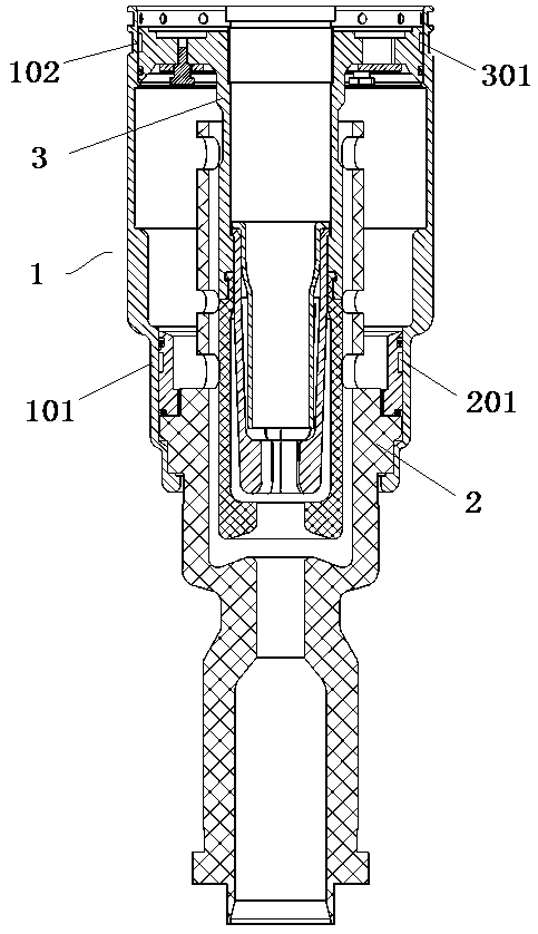
[0073] The specific embodiment 2 of the crimping device used for assembling the moving end assembly of the circuit breaker in this application: the difference between this embodiment and the specific embodiment 1 is that the bottom section of the workpiece positioning seat is provided with an inner flange, which is used to connect with The lower end surface of the moving main contact stops and cooperates to realize the axial positioning of the moving main contact by the workpiece positioning seat, relying on the small gap between the cavity wall of the moving main contact positioning cavity and the moving main contact, The contacts are limited in the radial direction to meet the crimping requirements of the moving contact assembly.

specific Embodiment 3

[0074] Specific embodiment 3 of the crimping device used to assemble the moving end assembly of the circuit breaker in this application: the difference between this embodiment and specific embodiment 1 is that the workpiece positioning seat is cylindrical, and the positioning cavity of the moving main contact The radial dimensions are consistent, and at this time, only an annular step for matching with the annular boss on the large-diameter section of the moving main contact is provided on the cavity wall of the moving main contact positioning cavity.

specific Embodiment 4

[0075] Specific embodiment 4 of the crimping device used to assemble the moving end assembly of the circuit breaker in this application: the difference between this embodiment and specific embodiment 1 is that the workpiece positioning seat is cylindrical, and the positioning cavity of the moving main contact The radial dimension is consistent, and the annular step matched with the annular boss on the small diameter section of the moving main contact has a larger radial dimension along the moving main contact positioning cavity.


PUM


Abstract

The invention relates to a crimping device for assembling a moving end assembly of a circuit breaker. The crimping device for assembling the moving end assembly of the circuit breaker comprises: a workpiece positioning seat which is provided with a moving main contact positioning cavity for positioning a moving main contact along the axial direction and the radial direction; an axial pressure applying devices for pressing and positioning the corresponding nozzle assemblies or valve assemblies to the moving main contact; and a first crimping device and a second crimping device, wherein the first crimping device is used for applying pressure to a first crimping part on the moving main contact, and the second crimping device is used for applying pressure to a second crimping part on the moving main contact. According to the crimping device, connection among the moving main contact, the nozzle assembly and the valve assembly can be realized, interference assembly of the valve assembly andthe moving main contact can also be realized, the operation is convenient, and the crimping efficiency is high.

Description

technical field [0001] The invention relates to a crimping device for assembling a moving end assembly of a circuit breaker. Background technique [0002] A moving end assembly in GIS includes a moving contact assembly and an insulating pull rod. The moving contact assembly includes three parts: a moving main contact, a spout assembly and a valve assembly. The three parts are connected by bolts. The insulating pull rod also includes two parts connected by bolts. part. However, the bolted connection method has the following problems: first, the assembly efficiency is low. Second, the weight of the moving end assembly is increased. The 3rd, cause the cost of moving end assembly to be higher. [0003] For example, if figure 1 A moving contact assembly is shown, the moving main contact 1 is provided with stop steps for axially stopping the spout assembly 2 and the valve assembly 3 respectively, and the outer peripheral surface of the spout assembly 2 is provided with a first...

Claims


Application Information

Patent Timeline
Patent Type & Authority Applications(China)
IPC IPC(8): H01H69/00
CPCH01H69/00
Inventor 黄建伟郭自豪黄坤鹏牛剑春王春良侯桂然李高欢徐凯张亚东徐锦举蒋会昂杜志宽杨晓凤张木壮张得六张一鸣吕留付
Owner HENAN PINGGAO ELECTRIC
Why Eureka
Try Eureka