
A squirrel cage conductor rotor brushless power feedback type permanent magnet governor
A technology of permanent magnet speed governor and conductor rotor, applied in the direction of permanent magnet clutch/brake, magnetic circuit, magnetic circuit rotating parts, etc. Energy saving effect and axial space saving effect
- Summary
- Abstract
- Description
- Claims
- Application Information
AI Technical Summary
Problems solved by technology
Method used
Image

Examples
Embodiment Construction
[0020] The technical solutions and beneficial effects of the present invention will be described in detail below in conjunction with the accompanying drawings.
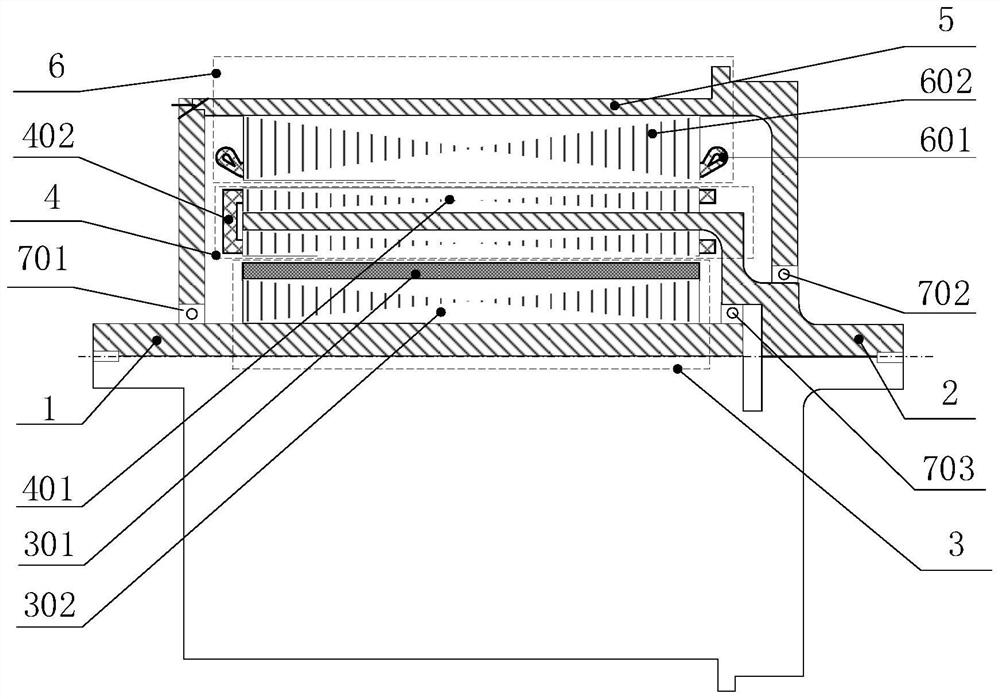
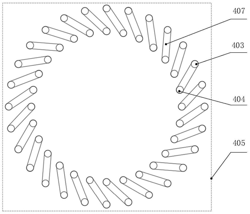
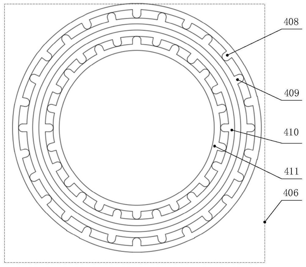
[0021] Such as figure 1 As shown, the present invention provides a squirrel-cage conductor rotor brushless power feedback type permanent magnet governor, which includes an input shaft 1 connected to the prime mover and an output shaft 2 connected to the load arranged on the same central shaft, the input shaft 1 is pierced with a permanent magnet rotor 3, and the output shaft 2 is pierced with a squirrel-cage structure conductor rotor 4 that can rotate relatively concentrically; the conductor rotor 4 is surrounded by a three-phase winding stator 6 fixed to the casing 5; the input shaft 1 is connected to the casing 5 through the first bearing 701, and the output shaft 2 is connected to the casing 5 through the second bearing 702; in order to enhance the stability of the mechanical mechanism between the rotors, the input...
PUM
 Abstract
Description
Claims
Application Information