Electric locomotive brake device

A brake device and technology for electric locomotives, applied in manual starting devices, transportation and packaging, railway car body parts, etc., can solve problems such as slow response speed, inconvenient operation for drivers and operators, and heavy handwheel mechanical brake devices, etc., to achieve Shorter braking distance and shorter braking reaction time

Inactive Publication Date: 2020-06-09
XIANGTAN ELECTRIC LOCOMOTIVE FACTORY
View PDF0 Cites 0 Cited by
  • Summary
  • Abstract
  • Description
  • Claims
  • Application Information

AI Technical Summary

Problems solved by technology

[0002] At present, the brake devices of industrial and mining electric locomotives mostly use hand wheel mechanical brake devices, which have problems such as heavy hand wheel mechanical brake devices, slow response speed, and inconvenient operation for drivers and operators.

Method used


Image

  • Electric locomotive brake device

Examples


Embodiment 1

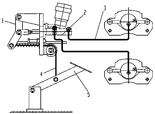
[0012] Embodiment 1, refer to figure 1 , the present invention includes a handwheel rotating threaded screw, a cross arm, a brake connecting rod, a brake shoe, a foot valve, a steel wire rope, a hydraulic master cylinder and a hydraulic connecting rod, and the handwheel rotating threaded screw is connected with the cross arm , the cross arm is connected with the brake shoe through the brake connecting rod, and the foot valve is connected with the hydraulic connecting rod through the wire rope.

Embodiment 2

[0013] Embodiment 2, refer to figure 1 , the hand wheel of the present invention rotates the threaded screw to drive the cross arm to move back and forth. The rest are the same as any other embodiment of the present invention or the combination of more than two embodiments.

Embodiment 3

[0014] Embodiment 3, refer to figure 1 , the cross arm of the present invention drives the left and right connecting rods to move so as to drive the bonding between the left and right brake shoes of the locomotive and the wheel tread. The rest are the same as any other embodiment of the present invention or the combination of more than two embodiments.


PUM


Abstract

An electric locomotive brake device mainly solves the technical problems that a hand wheel mechanical brake device adopted by an existing locomotive is cumbersome, low in response speed, inconvenientfor a driver and an operator to operate and the like. The device is characterized by comprising a hand wheel rotating threaded lead screw, a cross arm, a brake connecting rod, a brake shoe, a foot valve, a steel wire rope, a hydraulic master cylinder and a hydraulic connecting rod, the hand wheel rotating threaded lead screw is connected with the cross arm, the cross arm is connected with the brake shoe through the brake connecting rod, and the foot valve is connected with the hydraulic connecting rod through the steel wire rope. The brake device is mainly applied to industrial and mining electric locomotives.

Description

technical field [0001] The invention relates to a brake device for an electric locomotive. Background technique [0002] At present, the brake devices of industrial and mining electric locomotives mostly use hand wheel mechanical brake devices, which have problems such as heavy hand wheel mechanical brake devices, slow response speed, and inconvenient operation for drivers and operators. Contents of the invention [0003] The purpose of the present invention is to provide a brake device for electric locomotives that is bulky, slow in response, and inconvenient for drivers and operators to effectively improve the driving pleasure of the drivers for electric locomotives. [0004] The technical solution adopted by the present invention to solve its technical problems is: comprising hand wheel rotating threaded screw, cross arm, brake connecting rod, brake shoe, pedal valve, steel wire rope, hydraulic master cylinder and hydraulic connecting rod, said The threaded screw rod r...

Claims


Application Information

Patent Timeline
Patent Type & Authority Applications(China)
IPC IPC(8): B60T7/10B61H1/00
CPCB60T7/10B61H1/00
Inventor 俞晓阳任修勇阳智
Owner XIANGTAN ELECTRIC LOCOMOTIVE FACTORY
Why Eureka
Try Eureka