A biopharmaceutical filling system

A biomedicine and filling system technology, applied in the field of biomedicine filling system, can solve the problems of poor sealing and inconvenient filling of biomedicine

Active Publication Date: 2021-07-13
扬州凯芬机械有限公司
View PDF7 Cites 0 Cited by
  • Summary
  • Abstract
  • Description
  • Claims
  • Application Information

AI Technical Summary

Problems solved by technology

The utility model can adapt to the filling and capping requirements of medicine bottles of various specifications, and has a positioning device, which realizes the accuracy of capping, prevents the bottle mouth from being tightly sealed, and realizes a sterile and dust-free environment. Carry out three functions of filling / transferring / sealing, and the first robot is equipped with filling tubes and stopper sealing fixtures at the same time, and seals the stopper immediately after filling; but this equipment is not convenient for filling biomedicine in smaller bottles

Method used


Image

  • A biopharmaceutical filling system
  • A biopharmaceutical filling system
  • A biopharmaceutical filling system

Examples


specific Embodiment approach 1

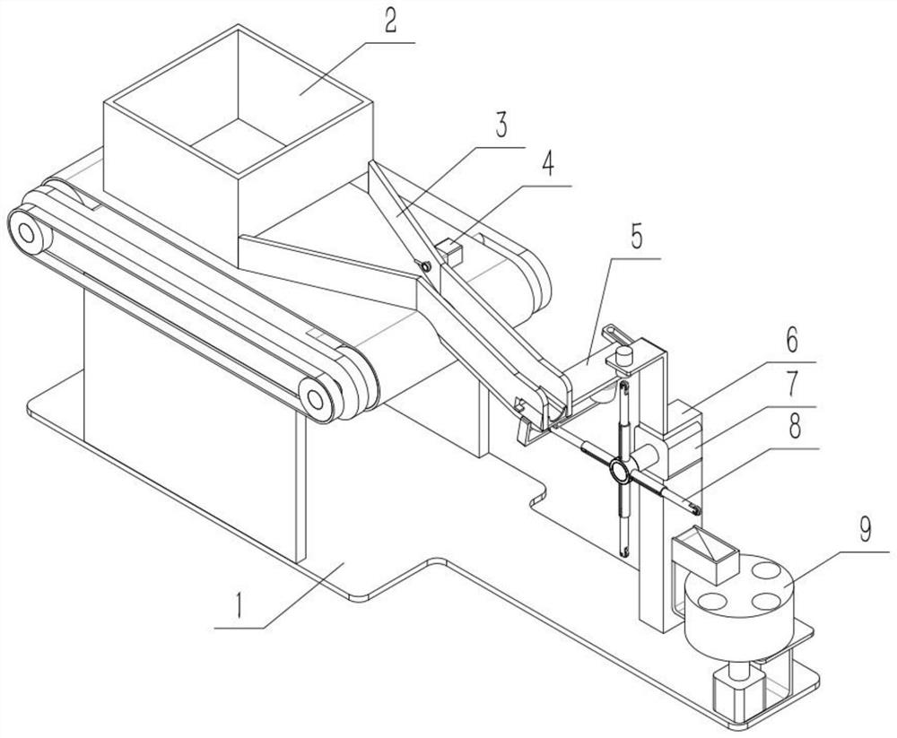
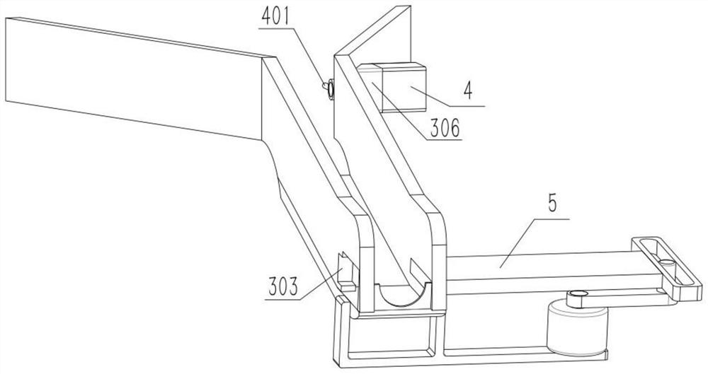
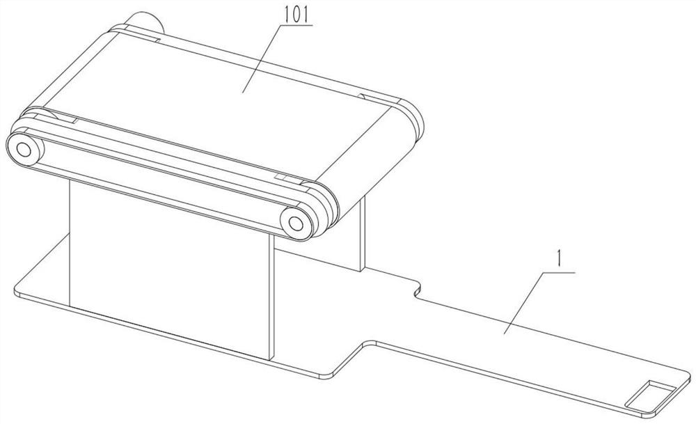
[0033] Such as Figure 1-12 As shown, a biomedical filling system includes a belt conveyor 101, a guide plate 3, a guide plate 301, a slide plate 302, a directional bottle outlet 303 and a baffle 305. The guide plate 3 is mirror-symmetrically arranged with two One, the right ends of the two guide plates 3 are fixedly connected with a guide plate 301 respectively, and the slide plate 302 is fixedly connected with the lower ends of the two guide plates 301, and the slide plate 302 is connected with the right end of the belt conveyor 101, and the orientation outlet 303 is set. On the guide plate 301 at the rear end, the position where the bottle mouth 303 is directed out is connected with the baffle plate 305 , and the baffle plate 305 is affixed to the right end of the downhill plate 302 . The belt conveyer 101 can adopt the existing traditional belt conveyer on the market, and the model can be purchased according to actual needs, and the vial used for filling will be used. The ...

specific Embodiment approach 2

[0035] Such as Figure 1-12 As shown, the biopharmaceutical filling system also includes a storage box 2, a bottle outlet 201 and a frame I202. The frame I 202 is installed on the belt conveyor 101, and the two ends of the bottle outlet 201 are connected with the left ends of the two guide plates 3. Place all the vials that need to be filled in the storage box 2. Only the upside-down vials can be sent out by setting the height of the bottle outlet 201. Combined with starting the belt conveyor 101, the accumulated vials are gradually exported out of the storage box in a single row. 2.

specific Embodiment approach 3

[0037] Such as Figure 1-12 As shown, the biopharmaceutical filling system further includes a sliding interface 304, the position of the sliding interface 304 is set correspondingly to the position of the oriented bottle outlet 303, and the sliding interface 304 is arranged on the guide plate 301 at the front end. Since a small bottle can pass between the two guide plates 301, it is more convenient to directly push out the small bottle from front to back through the sliding interface 304 than to move the small bottle above. Figure 5 Shown should only allow the vial with the bottle mouth to move out toward the left, and the bottom of the bottle with the bottle mouth toward the right will be against the directional bottle outlet 303 and cannot move.


PUM


Abstract

The invention relates to the field of filling, in particular to a biomedicine filling system. It includes a belt transport device, a guide plate, a guide plate, a sliding plate, a directional bottle outlet and a baffle plate, and the part for storing vials composed of a storage box cooperates with the transport part of the belt transport device to output stacked vials in a single layer; includes The guide part formed by the guide plate turns the single-layer transported vials into single-layer and single-row transported vials, ensuring that the bottle mouths are in a straight line; the sliding block is used to unify the orientation of the bottle mouths; the pick belt mechanism is used to facilitate spraying on the bottom of the bottles At the same time, the vials after coding will be transported to the next station in the same direction.

Description

technical field [0001] The invention relates to the field of filling, in particular to a biomedicine filling system. Background technique [0002] For example, the publication number is CN206872410U, a kind of robotic equipment for filling, transporting and sealing pharmaceuticals, including a transport system, a tray for placing material bottles and a robot for filling and / or sealing that cooperate with the transport system; the robot includes the first A robot and a second robot; the first robot is equipped with a filling nozzle and a rubber stopper fixture; the second robot is equipped with an aluminum cover fixture; the pharmaceutical filling, transporting and sealing robot equipment also includes a PLC controller. The utility model can adapt to the filling and capping requirements of medicine bottles of various specifications, and has a positioning device, which realizes the accuracy of capping, prevents the bottle mouth from being tightly sealed, and realizes a sterile...

Claims


Application Information

Patent Timeline
Patent Type & Authority Patents(China)
IPC IPC(8): B65B43/52B65B3/00B65G47/24B65G47/26
CPCB65B3/003B65B43/52B65G47/24B65G47/26B65G2201/0244
Inventor 车永翔
Owner 扬州凯芬机械有限公司
Why Eureka
Try Eureka