A photo frame sap material automatic turning mechanism

An automatic flipping and sap material technology, applied in the direction of conveyors, supporting frames, conveyor objects, etc., can solve the problems of inconvenient dust removal, inconvenient adjustment of flipping equipment, and inability to adapt to materials of different sizes, so as to achieve the effect of ensuring the filtration speed

Inactive Publication Date: 2021-09-07
洪敏燕
View PDF6 Cites 0 Cited by
  • Summary
  • Abstract
  • Description
  • Claims
  • Application Information

AI Technical Summary

Problems solved by technology

[0005] The purpose of the present invention is to solve the shortcomings of inconvenient adjustment, inability to adapt to materials of different sizes, and inconvenient dust removal when the overturning equipment is in use, and proposes an automatic overturning mechanism for photo frame sapwood

Method used


Image

  • A photo frame sap material automatic turning mechanism
  • A photo frame sap material automatic turning mechanism
  • A photo frame sap material automatic turning mechanism

Examples


Embodiment 1

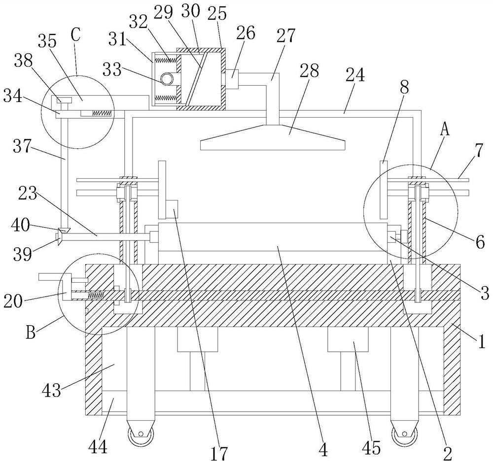
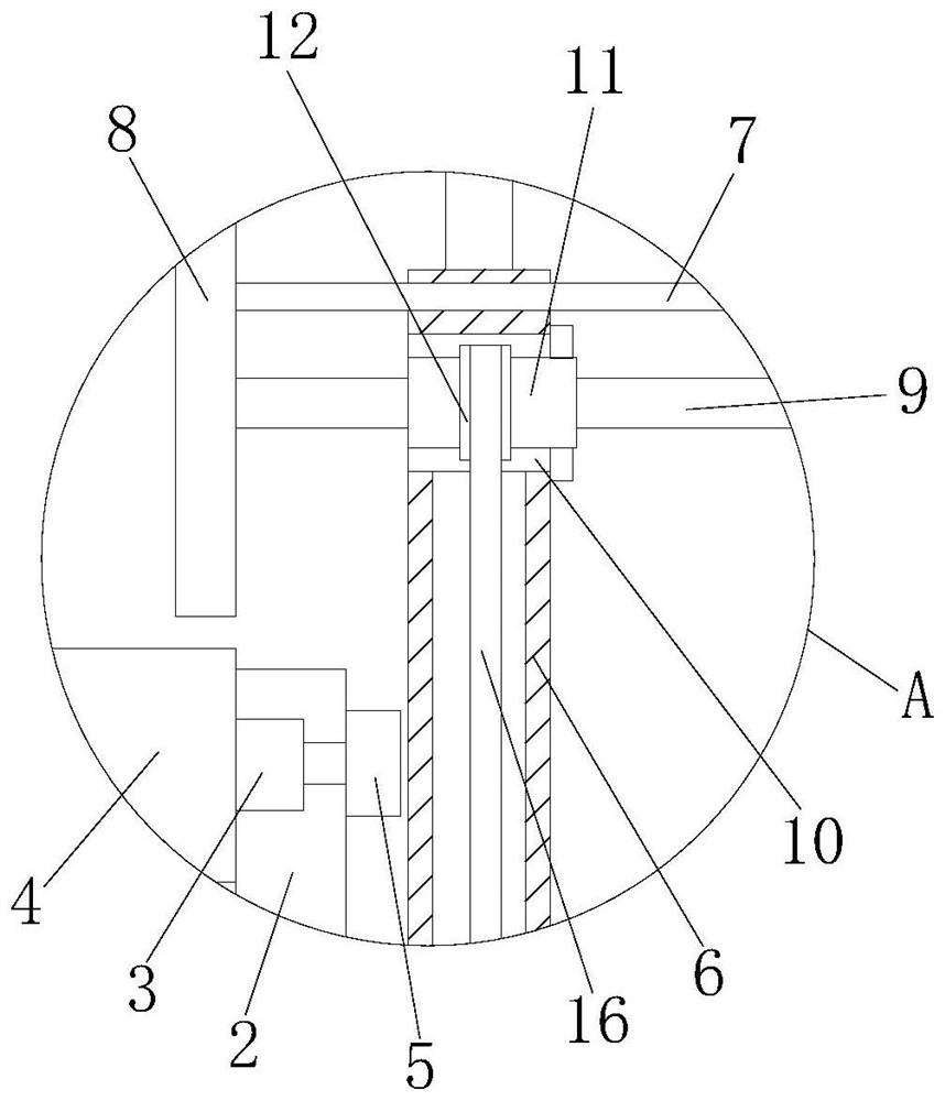
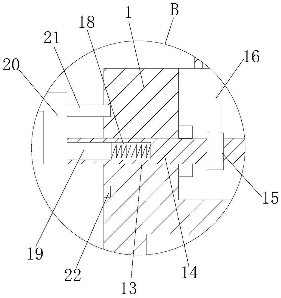
[0030] refer to Figure 1-5 , a photo frame sap material automatic turning mechanism, including a workbench 1, two fixed plates 2 are fixedly installed on the top of the workbench 1, and two rotating rollers 3 are installed on the side where the two fixed plates 2 are close to each other. The same conveyor belt 4 is arranged on the rotating roller 3, two side plates 6 are fixedly installed on the top of the workbench 1, and a slide plate 7 is slidably installed on the two side plates 6, and the sides of the two slide plates 7 that are close to each other are fixedly installed There is a baffle plate 8, one side of a baffle plate 8 in the two baffle plates 8 is fixedly installed with a stopper 17, and the side of the two baffle plates 8 away from each other is fixedly equipped with a transmission rod 9, and on the two side plates 6 Both are provided with rotating holes 10, and rotating tubes 11 are installed in the two rotating holes 10, and the two rotating tubes 11 are respec...

Embodiment 2

[0041] refer to Figure 1-5 , a photo frame sap material automatic turning mechanism, comprising a workbench 1, the top of the workbench 1 is fixed with two fixed plates 2 by screws, and two rotating rollers 3 are installed on the sides of the two fixed plates 2 that are close to each other, The two rotating rollers 3 are provided with the same conveyor belt 4, and the top of the workbench 1 is fixed with two side plates 6 by screws, and a slide plate 7 is slidably installed on the two side plates 6, and the two slide plates 7 are close to each other. Both sides are fixed with a baffle plate 8 by screws, one side of a baffle plate 8 in the two baffle plates 8 is fixed with a stopper 17 by a screw, and the sides of the two baffle plates 8 away from each other are all fixed with a screw. The transmission rod 9 is provided with a rotation hole 10 on the two side plates 6, and a rotation tube 11 is installed in the two rotation holes 10, and the two rotation tubes 11 are respectiv...


PUM


Abstract

The invention belongs to the technical field of photo frame production equipment, in particular to an automatic overturning mechanism for sap material of a photo frame. Aiming at the problems that the existing overturning equipment is inconvenient to adjust when in use, cannot adapt to materials of different sizes, and is inconvenient for dust removal, the present invention The following scheme is proposed, which includes a workbench. Two fixed plates are fixedly installed on the top of the workbench. Two rotating rollers are installed on the side of the two fixed plates close to each other. The same conveyor belt is arranged on the two rotating rollers. The workbench There are two side plates fixedly installed on the top of the two side plates, sliding plates are installed on both side plates, baffle plates are fixedly installed on the sides of the two slide plates close to each other, and one side of the baffle plate in the two baffle plates is fixedly installed There are stops. The invention can adapt to different sizes of sapwood, can process dust, shake off the dust on the filter net, ensure the filtering speed of the filter net, and can adjust the height of the conveyor belt to adapt to sapwood processing equipment of different heights .

Description

technical field [0001] The invention relates to the technical field of photo frame production equipment, in particular to an automatic turning mechanism for photo frame sap materials. Background technique [0002] Photo frame: similar to a square, the interior is empty, and the blank space is just for commonly used photos. It is mainly used for positioning the four sides of the photo and enhancing its aesthetics. It is also conducive to protecting the quality of the photo. Like a photo frame with glass, it can prevent Photo discoloration and yellowing, etc., are hollowed out decorative items. [0003] After searching, the patent document with the publication number CN207404436U discloses a photo frame sap material turning equipment, including the sap material processing equipment for producing L-shaped cross-section, the conveyor belt facing the exit of the sap material processing equipment and the The stop strips on both sides of the conveyor belt; on the inner side wall o...

Claims


Application Information

Patent Timeline
Patent Type & Authority Patents(China)
IPC IPC(8): B65G41/00B65G23/04B65G47/248B65G69/18
CPCB65G23/04B65G41/003B65G41/008B65G47/248B65G69/186
Inventor 洪敏燕
Owner 洪敏燕
Why Eureka
Try Eureka