Anti-slip trigger mechanism

A trigger mechanism and anti-slip technology, applied in the mechanical field, can solve problems such as potential safety hazards

Inactive Publication Date: 2020-06-09
PINGHU POINT HIGH RISE EQUIP +1
View PDF0 Cites 1 Cited by
  • Summary
  • Abstract
  • Description
  • Claims
  • Application Information

AI Technical Summary

Problems solved by technology

[0004] The purpose of the present invention is to solve the problem that in the existing lifting mechanism, when the reel motor stops rotating, the gondola will continue to slide due to inertia or the influence of its own gravity, and there are potential safety hazards

Method used


Image

  • Anti-slip trigger mechanism
  • Anti-slip trigger mechanism
  • Anti-slip trigger mechanism

Examples


Embodiment Construction

[0012] Below in conjunction with accompanying drawing and embodiment the present invention is further described:

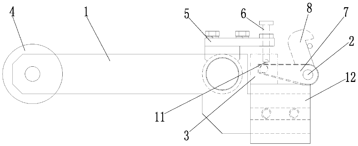
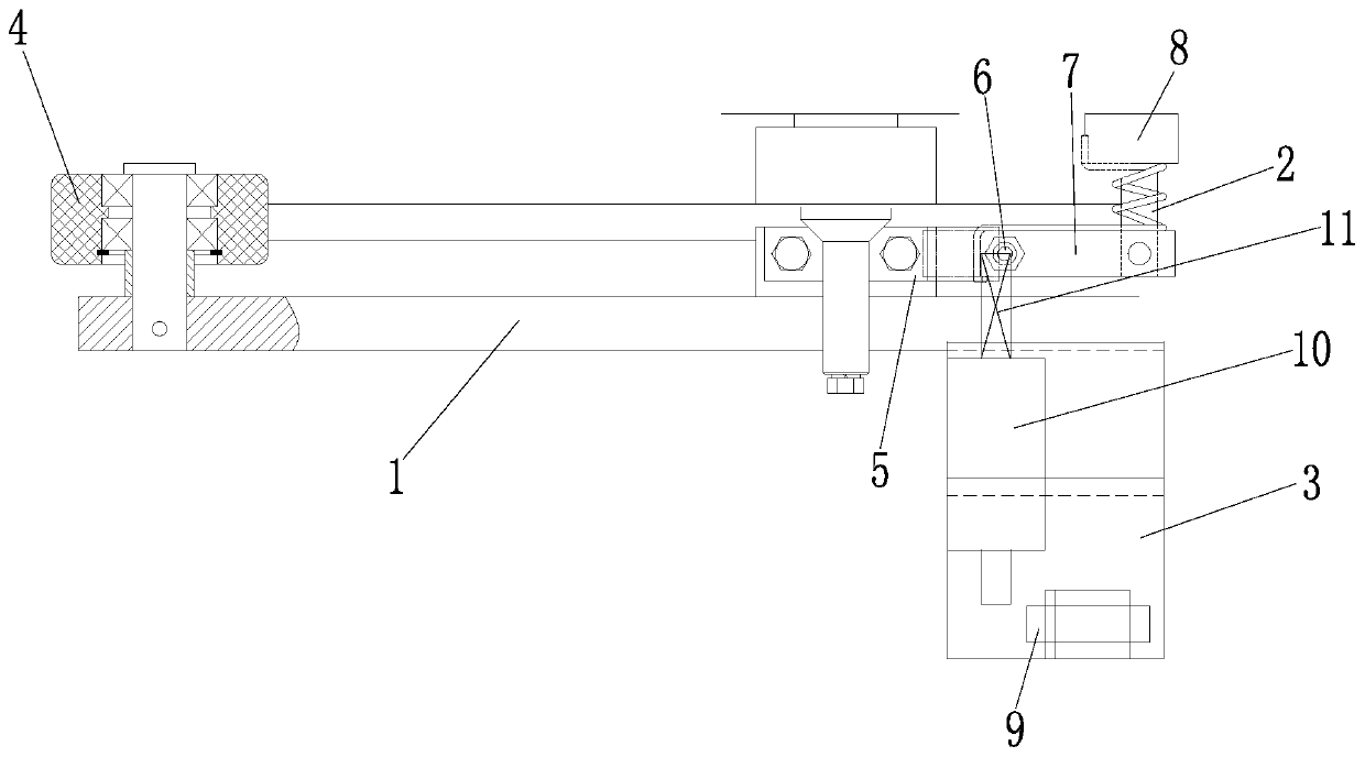
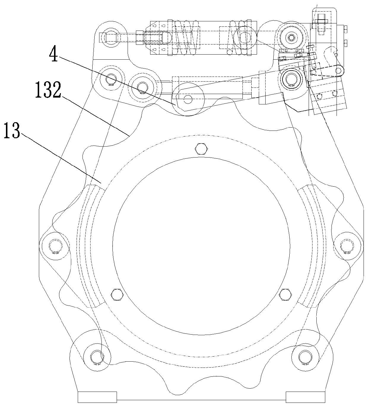
[0013] As shown in the figure, an embodiment of the anti-slip trigger mechanism of the present invention is provided, including a swing arm 1, a brake arm 2, and an angle aluminum bracket 3. The left end of the swing arm 1 is connected to an elastic wheel 4, and the swing arm 1 is also connected to a Press plate 5, trigger screw 6 is provided on press plate 5, small connecting plate 7 and trigger hook 8 are provided on brake arm 2, trigger screw 6 is located above small connecting plate 7, and small connecting plate 7 can be triggered by braking arm 2 The hook 8 moves, and the angle aluminum bracket 3 is provided with a photoelectric sensor switch 9 and an electromagnet 10. The photoelectric sensor 9 switch is used to detect whether the electromagnet 10 is normally sucked back. The electromagnet 10 is connected to the latch 11, and the position of the latch 11 corr...


PUM


Abstract

The invention discloses an anti-slip trigger mechanism. The anti-slip trigger mechanism comprises a swing arm, a brake arm and an angle aluminum bracket. The left end of the swing arm is connected with an elastic wheel, the swing arm is also connected with a pressing plate, the pressing plate is provided with a trigger bolt, the brake arm is provided with a small yoke plate and a trigger hook, thetrigger bolt is located above the small yoke plate, and the small yoke plate can drive the trigger hook to act through the brake arm. The angle aluminum bracket is provided with a photoelectric inductive switch and an electromagnet, the photoelectric inductive switch is used for detecting whether the electromagnet is normally attracted back or not, the electromagnet is connected with a plug pin,and the plug pin corresponds to the position between the trigger bolt and the small yoke plate. The anti-slip trigger mechanism can be used in a backup brake of a drum of a hoisting mechanism and solves the problem that a working platform continues to slide when a drum motor is off, and the possibility of drum motor misoperation is reduced when the backup brake locks the drum by arranging the photoelectric inductive switch.

Description

technical field [0001] The invention relates to the mechanical field, in particular to an anti-slip trigger mechanism. Background technique [0002] The lifting mechanism is a device that uses the drum motor to drive the drum to rotate, and realizes the lifting of the gondola through the wire rope wound on the drum. In actual use, when the reel motor stops rotating, the gondola will continue to slide due to inertia or the influence of its own gravity, posing a safety hazard. Contents of the invention [0003] The invention provides an anti-slip trigger mechanism. [0004] The purpose of the present invention is to solve the problem that in the existing lifting mechanism, when the reel motor stops rotating, the gondola will continue to slide due to inertia or the influence of its own gravity, and there is a potential safety hazard. [0005] The technical solution adopted by the present invention to solve the technical problem is: an anti-slip trigger mechanism, including ...

Claims


Application Information

Patent Timeline
Patent Type & Authority Applications(China)
IPC IPC(8): B66D1/54
CPCB66D1/54
Inventor 兰阳春
Owner PINGHU POINT HIGH RISE EQUIP
Why Eureka
Try Eureka