Eureka AIR delivers breakthrough ideas for toughest innovation challenges, trusted by R&D personnel around the world.

Lock catch structure

A lock and tongue technology, applied in building locks, electric alarm locks, building structures, etc., can solve the problem of being unable to control multiple doors or windows at the same time, and achieve the effect of simple structure and convenient operation.

Pending Publication Date: 2020-06-09
NINGBO WANGTONG LOCKS
View PDF2 Cites 1 Cited by
  • Summary
  • Abstract
  • Description
  • Claims
  • Application Information

AI Technical Summary

Problems solved by technology

[0004] In view of the above problems, the present invention proposes a lock structure, which solves the defect that the existing lock structure cannot simultaneously control multiple doors or windows

Method used


Image

  • Lock catch structure
  • Lock catch structure
  • Lock catch structure

Examples


Embodiment 1

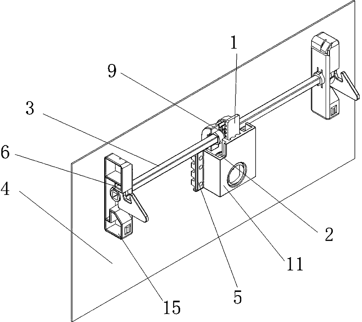
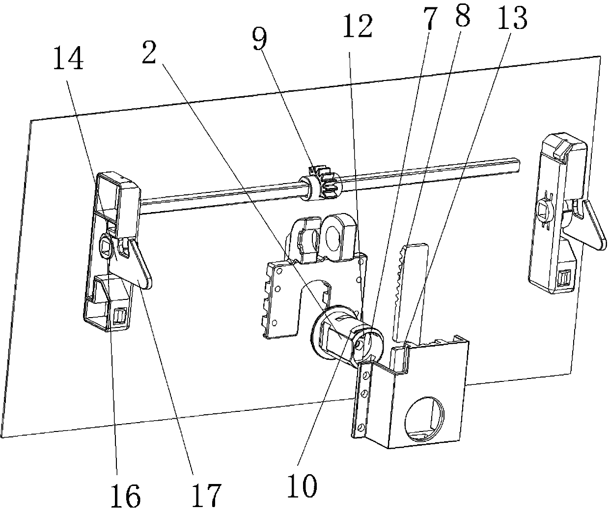
[0032] Such as figure 1 , figure 2 As shown, the technical solutions adopted by the present invention are as follows:

[0033] A lock buckle structure includes a lock tongue 1, a lock core 2, a rotating rod 3, a door panel 4, a lock shell 5 and a pair of hook assemblies 6. One end of the lock core is equipped with a connecting block 7, and one side of the connecting block drives the connecting bolt for reciprocating movement of the bolt. A rack 8 is provided on one side of the bolt; a gear is installed on the rotating rod 9. The gear meshes with the rack, and the pair of hook components are arranged at both ends of the rotating rod. The lock shell is fixed on the door panel, and the lock core is installed in the lock shell. The lock core is provided with a perforation 10 for easy installation of the bolt; a rear cover 11 is installed at the rear end of the lock shell. A convex post 12 is provided on the connecting block, and the convex post is installed on the outer edge of th...

Embodiment 2

[0038] A lock structure includes:

[0039] A lock tongue

[0040] A lock cylinder; one end of the lock cylinder is equipped with a connecting block, one side of the connecting block is used to drive the lock tongue to reciprocate, and one side of the lock tongue is provided with a rack;

[0041] A rotating rod; a gear is mounted on the rotating rod, and the gear meshes with a rack; and

[0042] At least one hook assembly is installed on the rotating rod.

Embodiment 3

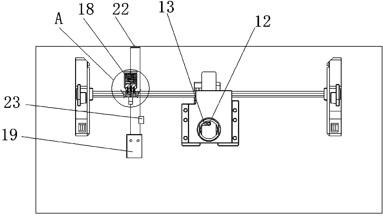
[0044] Such as image 3 , Figure 4 , Figure 5 with Image 6 As shown, the difference between Embodiment 3 and Embodiment 1 is that the locking structure further includes an automatic locking assembly 18, a battery 19, a fixed conductive block 20, a brush sheet 21, a control switch 22 and a buzzer 23. The battery and the fixed conductive block are fixed on the inner side of the door panel, and the power source is sequentially connected with the fixed conductive block, the brush sheet, the automatic locking component, the control switch and the buzzer through the wires. One end of the brush piece is electrically connected to a fixed conductive block. The rotating rod is a hexagonal prism. The rotating rod includes a fixing member 24 and two insulating members 25 located on both sides of the fixing member. A ring-shaped first magnet 26 and a ring-shaped second magnet 27 are respectively provided in the edge surfaces of the two phases. The S pole of the first magnet faces outward...


PUM


Abstract

The invention discloses a lock catch structure. The lock catch structure includes a lock bolt, a lock cylinder, a rotating rod and at least one hook component; a connecting block is installed at one end of the lock cylinder, one side of the connecting block is connected with the lock bolt in a drive mode for driving the lock bolt to reciprocate, and a rack is arranged on one side of the lock bolt;a gear is installed on the rotating rod, and the gear meshes with the rack; and the hook components are installed on the rotating rod. According to the lock catch structure, parallel movement of thelock bolt is converted into gear rotation movement by a gear rack structure, then the rotating rod is driven to rotate, the hook components are driven to rotate to realize locking and unlocking of devices to be locked, the single lock cylinder can simultaneously control the multiple hook components, and then the multiple devices to be locked are locked or unlocked, so that the defect that existinglock catch structures cannot simultaneously control a plurality of doors or windows is overcome.

Description

Technical field [0001] The invention relates to the field of lock production, in particular to a lock structure. Background technique [0002] The existing patent document with the publication number CN101148961 discloses a concealed buckle lock, so as to install the buckle lock in the horizontally drawn inner window frame, and at the same time, a buckle rod seat is provided in the matching outer window frame, so when hidden When the buckle lock is activated, the hook piece can be unscrewed and the hook buckles the buckle rod to achieve the locking effect. The hidden buckle lock is composed of a base, an upper hook piece, a lower hook piece, an upper snap button, a lower snap button, a gear plate, an upper rod, a lower rod and a cover plate. The aforementioned components are assembled in the base, covered with a cover plate and riveted, wherein the upper hook piece and the lower hook piece are connected to the upper and lower rods through the upper and lower buttons, and the pul...

Claims


Application Information

Patent Timeline
Patent Type & Authority Applications(China)
IPC IPC(8): E05B15/00E05B15/10E05B45/06E05B47/00E05B63/14
CPCE05B15/00E05B15/10E05B45/06E05B47/0038E05B63/146
Inventor 韩文杰王壤
Owner NINGBO WANGTONG LOCKS
Why Eureka
Eureka Blog
Learn More