
slide structure

A slide table and slide rail technology, applied in the direction of transmission, belt/chain/gear, mechanical equipment, etc., can solve the problems of large structure volume, lack of stability, loss of precision of slide table, etc., to save assembly space, Increase practicality and avoid the effect of power attenuation

Active Publication Date: 2021-08-10
CHIUAN YAN TECH
View PDF7 Cites 0 Cited by
  • Summary
  • Abstract
  • Description
  • Claims
  • Application Information

AI Technical Summary

Problems solved by technology

[0002] Now, the common sliding table structure, please refer to Figure 8 As shown, wherein, between the existing sliding table 50 and the shaft 511 of the drive motor 51, a coupling 52 must be assembled as a connection interface, and then a screw 53 is driven to rotate through the coupling 52, and Utilize the rotating screw 53 to link a sliding seat 54 to slide on the sliding table 50, and then through the rotation of the screw 53, the sliding seat 54 can be displaced along the screw 53 to achieve the guide on the processing equipment. Transmission, but this kind of existing structure must reserve space for assembling the shaft coupling 52, and the screw 53 will also be connected to the shaft coupling 52, resulting in a larger volume of the sliding table structure and more space. Moreover, the sliding seat 54 slides along the displacement of the screw rod 53, so that the displacement stroke is longer and lacks stability. The above-mentioned displacement stroke is found in practical application experience. The rods 511 are combined, and there is unavoidably a progressive tolerance among the three. The slide table structure may lose precision due to the combined error between the coupling 52, the driving motor 51 and the shaft rod 511. However, a little The error will seriously affect the displacement stroke. In addition, in terms of transmission efficiency, when the output power of the shaft 511 of the drive motor 51 is transmitted through the coupling 52, a certain degree of power attenuation will also occur due to the combination. question

Method used


Image

  • slide structure
  • slide structure
  • slide structure

Examples


Embodiment Construction

[0031] The present invention will be further described below in conjunction with the accompanying drawings and specific embodiments, so that those skilled in the art can better understand the present invention and implement it, but the examples given are not intended to limit the present invention.

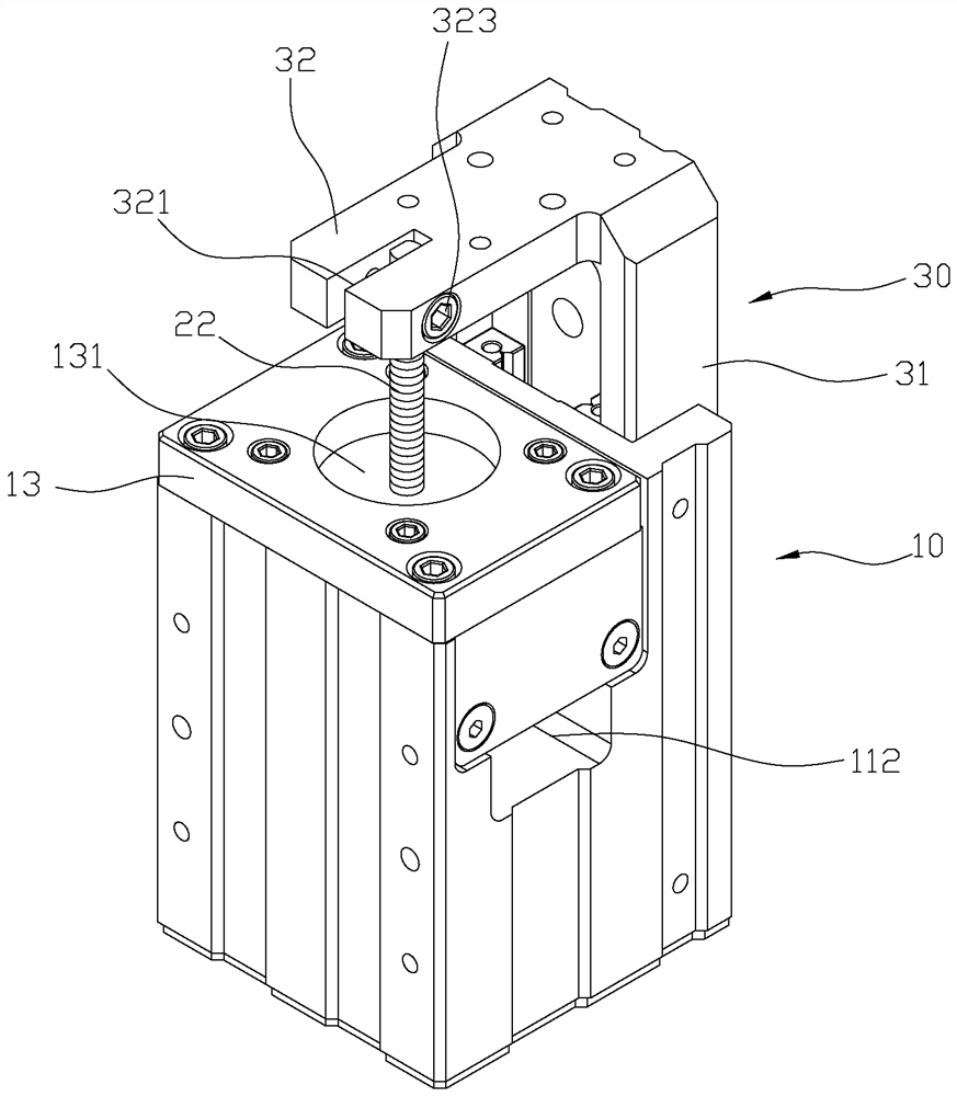
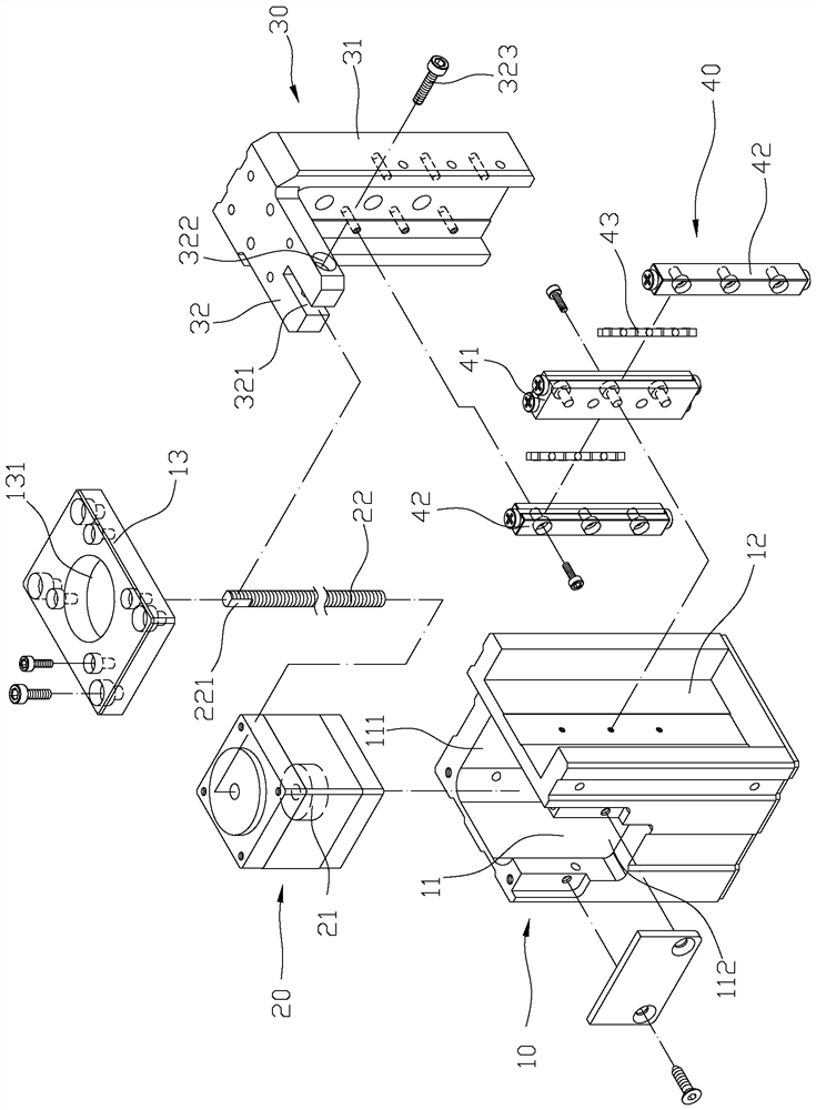
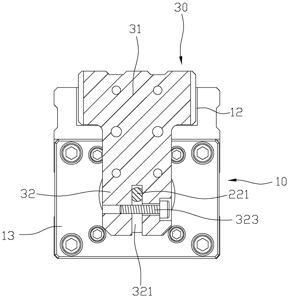
[0032] First, please see figure 1 As shown, a slide table structure includes: a base 10, a motor 20, a slide seat 30 and a miniature slide rail group 40, wherein the base 10 is hollow with an accommodating space 11, and on a A rail groove 12 is provided on the outside, and one end of the accommodating space 11 communicates with the outside to form an opening 111, and a through hole 112 is opened to the side. The opening 111 is also provided with a fixing plate 13, and the fixing plate 13 has a central perforation 131, the motor 20 is fixed in the accommodating space 11 of the base 10, the motor 20 is internally linked with a nut 21 to operate, and the nut 21 drives a screw 22 to ...


PUM


Abstract

The present invention provides a sliding table structure, which at least includes a base, a motor and a sliding seat, wherein, the sliding table uses a base and a motor to achieve the sliding displacement of the sliding seat, so as to achieve the application of automatic operation, and the base The seat presets a housing space for the installation of the motor. The depth of the housing space is greater than the axial length of the motor, and can be used as the retraction stroke of the screw, so that the structure of the slide table can not only save the assembly space of the coupling, but also has It helps to reduce the volume of the structure, and at the same time shortens the driving stroke of the slide table, greatly improves the stability of the structure, can be applied to more sophisticated operating equipment, and increases the practicability of the structure.

Description

technical field [0001] The present invention relates to a slide table structure, especially a slide table structure with small volume and capable of shortening working stroke. Background technique [0002] Now, the common slide table structure, please refer to Figure 8 As shown, wherein, between the existing sliding table 50 and the shaft 511 of the drive motor 51, a coupling 52 must be assembled as a connection interface, and then a screw 53 is driven to rotate through the coupling 52, and Utilize the rotating screw 53 to link a sliding seat 54 to slide on the sliding table 50, and then through the rotation of the screw 53, the sliding seat 54 can be displaced along the screw 53 to achieve the guide on the processing equipment. Transmission, but this kind of existing structure must reserve space for assembling the shaft coupling 52, and the screw 53 will also be connected to the shaft coupling 52, resulting in a larger volume of the sliding table structure and more space. ...

Claims


Application Information

Patent Timeline
Patent Type & Authority Patents(China)
IPC IPC(8): F16H25/24
CPCF16H25/24
Inventor 邱毓英林炳宏张嘉杰
Owner CHIUAN YAN TECH
Learn More