
Piezoelectrically Driven Dual-Axis Tilting Sample Holder for Transmission Electron Microscopy

An electron microscope, piezoelectric drive technology, applied in circuits, discharge tubes, electrical components, etc., can solve the problems of a large number of transmission parts, raising or lowering, connecting rods, etc., achieving small size, simple structure, and rapid response. Effect

Active Publication Date: 2018-06-05
ZHEJIANG UNIV
View PDF6 Cites 0 Cited by
  • Summary
  • Abstract
  • Description
  • Claims
  • Application Information

AI Technical Summary

Problems solved by technology

[0005] The disadvantage of this kind of sample rod is that the rotation of the sensor stage around the Y axis is driven by the Y-axis tilting driver arranged at the end of the sensor stage. The Y-axis tilting driver includes a rotating shaft, a rotating block and a connecting rod connecting the sensor stage. , when the rotating shaft and the rotating block rotate, the connecting rod rises or falls, thereby driving one end of the sensor carrier to rise or lower, and realize the tilting of the sensor carrier around the Y axis. This driving method has a large volume of the driving mechanism and transmission parts The quantity is large, and the maximum angle of inclination is difficult to exceed 30 o The shortcoming of this is that in many cases, a certain crystal direction of the sample of interest cannot be parallel to the electron beam, so that high-resolution images at the atomic level cannot be obtained

Method used


Image

  • Piezoelectrically Driven Dual-Axis Tilting Sample Holder for Transmission Electron Microscopy
  • Piezoelectrically Driven Dual-Axis Tilting Sample Holder for Transmission Electron Microscopy
  • Piezoelectrically Driven Dual-Axis Tilting Sample Holder for Transmission Electron Microscopy

Examples


Embodiment Construction

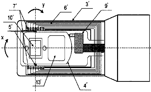
[0019] Such as image 3 As shown, the piezo-electrically driven dual-axis tilting sample rod for transmission electron microscope mainly includes a handle 5, a sample rod shaft 4, a sample rod head 1 and a sample cup 2 for loading samples. The sample cup 2 and Axis 9 is fixed, The shaft 9 is rotatably mounted on the head end 1 of the sample rod. The signal connection port of the sample rod 4 is arranged on the handle 5 . The sample cup 2 is mounted on the sample rod head end support 3 of the sample rod head end 1 .

[0020] Sample rod tip 1 set drive The drive member 10 of shaft 9 step-by-step rotation, drive member 10 and The shaft 9 is in close contact, and when the driving member 10 moves from the first position to the second position, Axis 9 steps an angular travel ; When the driver 10 is reset from the second position to the first position, The shaft 9 is fixed; the drive member 10 moves from the first position to the second position and resets from the seco...


PUM


Abstract

A piezoelectric driving double-shaft tilt sample rod for a transmission electron microscope provided by the invention mainly comprises a holding handle, a sample rod body, a sample rod head and a sample bottle configured to holding a sample. The sample bottle is fixed with a [Beta] shaft, the [Beta] shaft is rotatably connected with the sample rod head; the sample rod head is provided with a driving piece configured to drive the [Beta] shaft to rotate step by step, the driving piece is tightly contacted with the [Beta] shaft, and when the driving piece is moved from a first position to a second position, the [Beta] shaft steps into an angle stroke [Theta]'; when the driving piece is reset from the second position to the first position, the [Beta] shaft is fixed; and the driving piece is moved from the first position to the second position and reset from the second position to the first position to form a movement period, the rotation angle of the [Beta] shaft is equal to N*[Theta]', wherein N is the number of the movement period. According to the invention, the size of a device configured to drive the sample rod to rotate around the [Beta] shaft is small, and the inclination angle can exceed 30 degrees.

Description

technical field [0001] The invention relates to components of a transmission electron microscope, in particular to a biaxial tilting sample rod for a transmission electron microscope. technical background [0002] Transmission Electron Microscope (hereinafter referred to as TEM) is a large-scale experimental device for characterizing the microstructure of materials. It can simultaneously analyze the microstructure, crystal structure, and constituent elements of materials. The imaging principle is that the high-energy electron beam penetrates the sample, the transmitted electron beam is focused and amplified, and the detector is used to collect the signal and form an image. Modern high-resolution transmission electron microscopes can usually achieve atomic-level resolution, especially the rapid development of spherical aberration correction technology in the past five years makes the limit resolution of TEM reach 50 pm. However, it is often difficult to reach the limit resol...

Claims


Application Information

Patent Timeline
Patent Type & Authority Patents(China)
IPC IPC(8): H01J37/20
Inventor 王宏涛刘嘉斌
Owner ZHEJIANG UNIV
Learn More