
Lock pin

A technology of lock cylinders and movable parts, which is applied to building locks, locks controlled by non-mechanical transmission, buildings, etc., can solve problems such as incompatibility, difficulty, and large capacity of power supply systems, so as to improve reliability and service life, and drive The effect of small stroke and reduced failure rate

Inactive Publication Date: 2008-08-13
HUNAN HONGDA TECH
View PDF4 Cites 0 Cited by
  • Summary
  • Abstract
  • Description
  • Claims
  • Application Information

AI Technical Summary

Problems solved by technology

[0003] The electronic locks currently on the market, whether they work with AC or DC, generally have a working power consumption of several watts (W) to tens of watts (that is, the working voltage is mostly 12-24V, and the working current is 0.2-2A). Due to low efficiency and high power consumption, this type of electronic lock requires a large capacity of the power supply system, so it cannot match the microelectronic control circuit with continuously reduced volume, weight, and power consumption, which also leads to very strict or frequent power consumption requirements in some applications. It is almost impossible to apply in the occasion of power failure, which restricts the popularization and replacement of electronic control locks. Therefore, the application of electronic locks has been limited to high-end commercial places such as hotels and office buildings, and cannot be widely used in homes; Driven by a motor, it is driven by gears and racks. The electromechanical structure is relatively complex, and installation and maintenance require certain professional skills, which is difficult; the entire mechanism consumes high power, and when a fault occurs, the motor self-locking will block the entire mechanism , so this type of electronic lock must be equipped with an ordinary mechanical unlocking mechanism
For the existing ordinary mechanical lock, if it is to be converted into an electronic lock, the entire lock can only be replaced in the prior art, so it cannot be well integrated with the traditional mechanical lock, the replacement cost is high, and it is not conducive to popularization and application.

Method used


Image

  • Lock pin
  • Lock pin
  • Lock pin

Examples


Embodiment 1

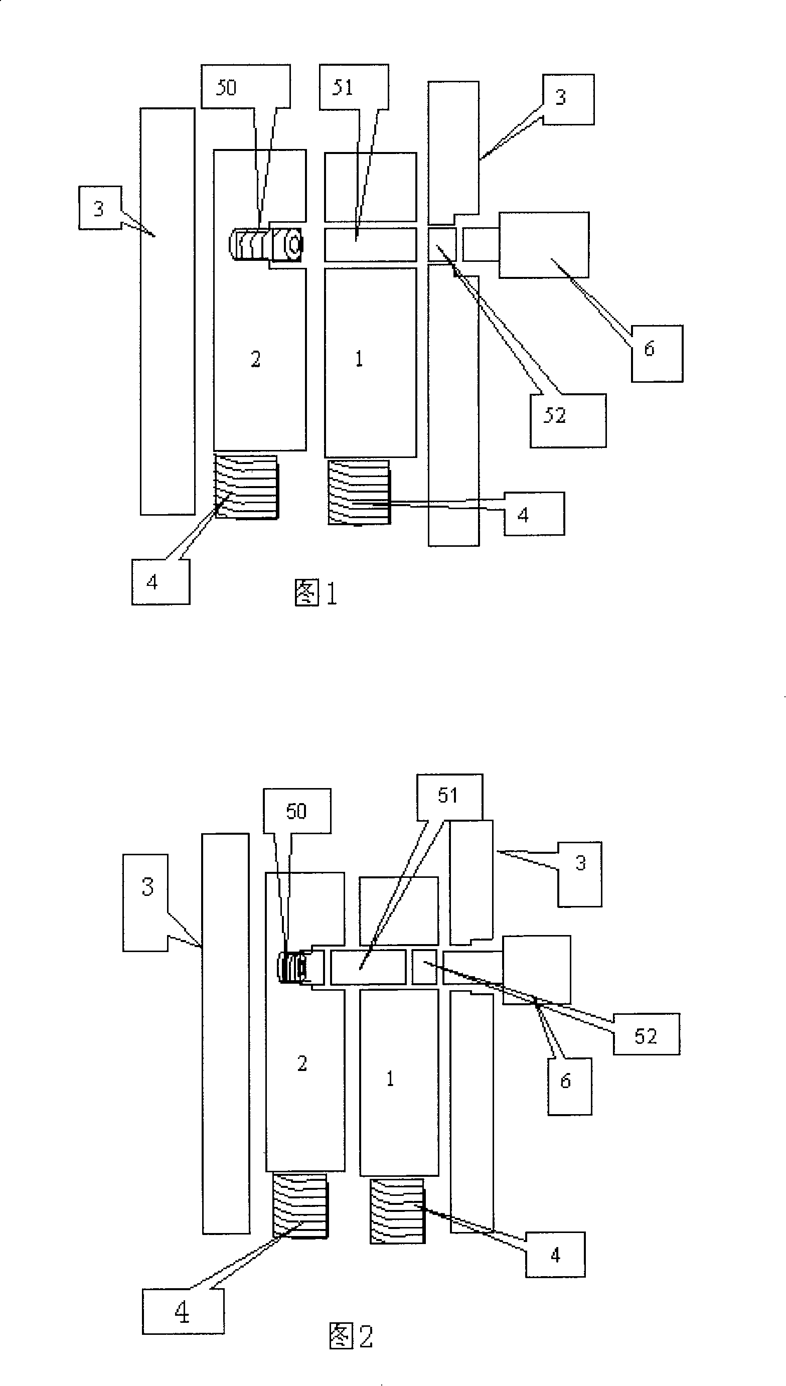
[0042] Embodiment 1: The first movable part 1 and the second movable part 2 are set side by side in the housing 3; the clutch part is composed of a first clutch pin 51 and a second clutch pin 52, and the guide hole is a blind hole; the bottom of the blind hole is located at The inner wall of the second movable part passes through the first movable part and opens to the casing, and a through hole is respectively formed on the first movable part and the casing; the elastic part is placed in the pin hole of the first movable part. As shown in Fig. 1 and Fig. 2, the separation and relative locking states of the first movable part 1 and the second movable part 2 are respectively, and the relative movement of the first movable part 1, the second movable part 2 and the housing 3 is shown in Fig. 1, The direction indicated by the arrow in Figure 2. Fig. 1 is a state where the elastic pin 50 is naturally stretched, and the first movable part 1, the second movable part 2, and the housin...

Embodiment 2

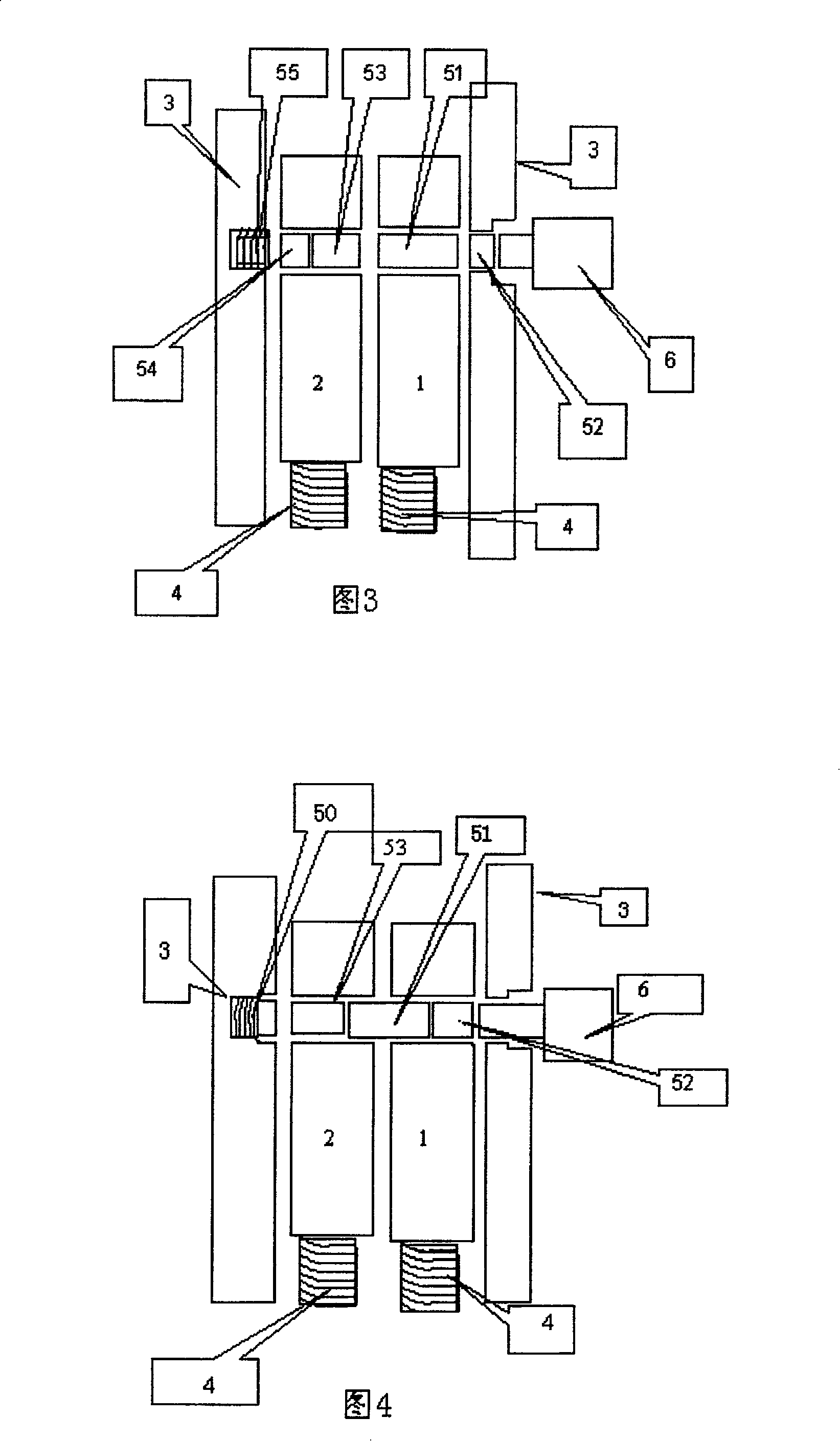
[0043] Embodiment 2: As shown in Figure 3 and Figure 4, it is a modification of Embodiment 1. The bottom of the blind hole is located on the side wall of the housing 3, passing through the first movable part 1 and the second movable part 2, and the opening is located at the side wall of the housing. On the other side wall, a through hole is respectively formed on the first movable part, the second movable part and the casing. The clutch includes a first clutch pin 51 , a second clutch pin 52 , a third clutch pin 53 , a fourth clutch pin 54 and a spring 55 . In the natural state, the first movable part 1, the second movable part 2, and the housing 3 are in a non-interfering and relatively independent state; the first clutch pin 51 is completely in the through hole of the first movable part, and its length is equal to that of the first movable part. Piece 1 thickness. The third clutch pin 53 and the fourth clutch pin 54 are completely in the through hole of the second movable p...

Embodiment 3

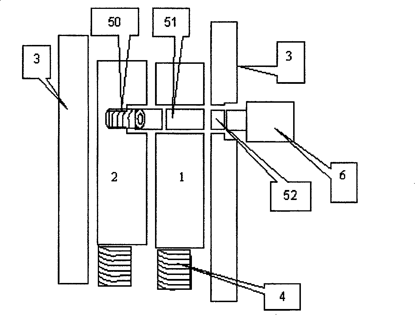
[0044] Embodiment three: as Figure 5 , Figure 6 as shown, Figure 5 When the elastic pin 50 is stretched naturally, the elastic pin 50 is located between the second movable part 2 and the first movable part 1 to lock the two with each other, and the two are in a freely movable state relative to the housing 3 . Figure 6 , the driving output shaft of the driving device 6 stretches out, drives the second clutch pin 52 into the through hole of the first movable part 1, and then presses the first clutch pin 51, and the first clutch pin 51 compresses the elastic pin 50, so that the first The movable part 1, the second movable part 2, and the housing 3 are in a state of being independent and freely movable. The length of the first clutch pin 51 plus the second clutch pin 52 is equal to the thickness of the first movable part 1 , and the length of the second clutch pin is equal to the axial displacement of the drive output shaft of the drive device 6 .


PUM


Abstract

This invention discloses a lock pin structure, which comprises the first movable part (1), the second movable part (2), shell (3), clutch mechanism and resetting-mechanism (4); wherein the first movable part and the second movable part are set inside the shell, and by the clutch mechanism, it produces the locking or hands-off relationship between the first movable part, the second movable part and the shell; the resetting-mechanism makes the first movable part and the second movable part restoring to the initial condition. Said structure is convenient to back-up, and can form several independent back-up component without increasing voltage; besides, the invention can be used directly in the car door and safety deposit box, compatible with kinds of electrical controlling system.

Description

【Technical field】: [0001] The invention relates to a lock cylinder structure. 【Background technique】: [0002] Electronic lock is a new type of lock that is more and more widely used, and it is an updated product of traditional mechanical lock. [0003] The electronic locks currently on the market, whether they work with AC or DC, generally have a working power consumption of several watts (W) to tens of watts (that is, the working voltage is mostly 12-24V, and the working current is 0.2-2A). Due to low efficiency and high power consumption, this type of electronic lock requires a large capacity of the power supply system, so it cannot match the microelectronic control circuit with continuously reduced volume, weight, and power consumption, which also leads to very strict or frequent power consumption requirements in some applications. It is almost impossible to apply in the occasion of power failure, which restricts the popularization and replacement of electronic control ...

Claims


Application Information

Patent Timeline
Patent Type & Authority Patents(China)
IPC IPC(8): E05B47/00E05B15/00
CPCE05B47/0611
Inventor 徐文祥
Owner HUNAN HONGDA TECH
Learn More