Self-adjusting crimping pliers

A crimping pliers, self-adjusting technology, applied in circuit/collector parts, electrical components, circuits, etc., can solve the problems of no self-adjusting function, lack of reed space, lack of versatility, etc., to achieve beautiful appearance , Reduce the volume, the effect of convenient connection

Inactive Publication Date: 2016-02-24
乐清市菲尔科工具有限公司
View PDF4 Cites 0 Cited by
  • Summary
  • Abstract
  • Description
  • Claims
  • Application Information

AI Technical Summary

Problems solved by technology

The existing crimping pliers for crimping tubular terminals generally do not have the function of self-adjustment, and need to adjust the size according to the size of the terminal before crimping. The operation is cumbersome, the applicable area is narrow, and it does not have universality.
[0003] The existing crimping pliers capable of self-adjustment are generally manually operated manual pliers. This kind of crimping pliers requires a very long reed, and one of the handles of the manual pliers needs to be used as an action handle instead of a reed. The reed can only be set in the fixed handle. In order to ensure the elasticity of the reed and the pressure when crimping the wire, the reed needs to be very long. If this kind of pliers is to be added to the pneumatic or electric pliers, then There will be a lack of space to accommodate the reed, so there are no self-adjusting pneumatic or electric pliers on the market today
Manual pliers have certain requirements for physical strength when used many times, especially in wire harness processing and terminal crimping production enterprises. Workers need to use manual pliers for a long time, which is labor intensive and affects production efficiency.

Method used


Image

  • Self-adjusting crimping pliers
  • Self-adjusting crimping pliers
  • Self-adjusting crimping pliers

Examples


Embodiment Construction

[0039] The present invention will be further described below in conjunction with the accompanying drawings.

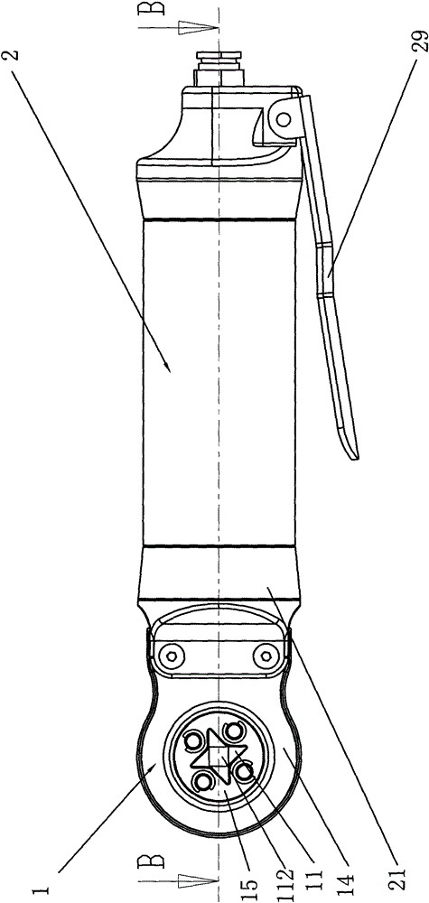
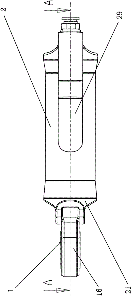
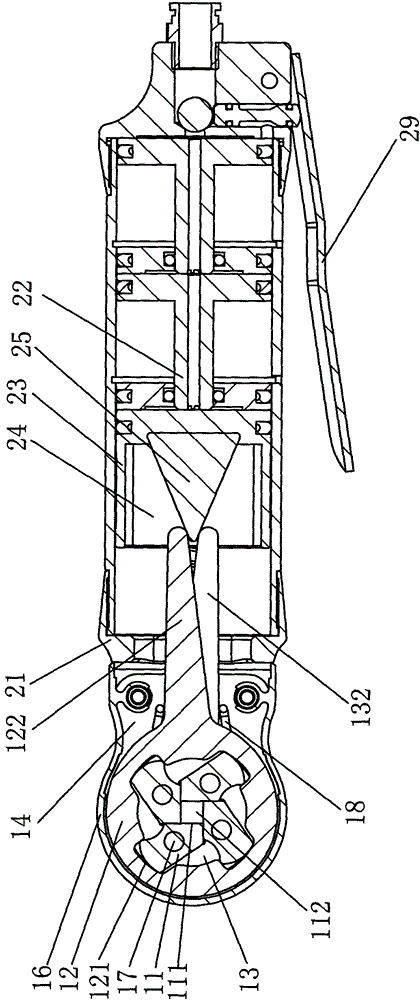
[0040] Such as Figure 1-6 As shown, the specific embodiment 1 of the present invention is a kind of pneumatic self-adjusting type wire crimping pliers, including a pliers head 1 and a double force cylinder 2, and the pliers head 1 includes a pressure tooth 11, a ring gear 12, a rotating plate 13, a support plate 14, Rotating cover 15, dust cover 16 and rotating shaft 17, four tooth grooves 121 are evenly formed on the inner side of ring gear 12, and a tooth arm 122 is formed on the outer side of ring gear 12 toward one end, and four pressure teeth 11 are arranged in ring gear 12. The tail part of 11 is arranged in the alveolar 121 to cooperate with the alveolar wall. The front end of the pressing tooth 11 is a crimping surface 111, and the crimping surfaces 111 surround each other to form a crimping port 112. The center of the pressing tooth 11 is hinged on the horizo...


PUM


Abstract

The invention relates to a self-adjusted wire crimper. The self-adjusted wire crimper comprises a crimper head and a driving mechanism. The crimper head comprises a plurality of pressing teeth, a gear ring, a rotating plate and supporting plates. The pressing teeth are evenly arranged in the gear ring. The rotating plate is arranged two sides of the pressing teeth and two sides of the gear ring. The pressing teeth are in linkage matching with the rotating plate and the gear ring at the same time. A leaf spring is integrally formed on the rotating plate. The two supporting plates are correspondingly connected to the driving mechanism. The rotating plate is connected to the inner side of each supporting plate to form rotating matching. Both the leaf spring and the gear ring are in linkage with the driving mechanism. Because the rotating plate and the leaf spring are integrally formed, when different diameters of terminals are connected in a pressed mode, elastic deformation of the leaf spring is generated so that the pressing connection motion can be completed, and the self-adaption purpose is achieved; furthermore, because the rotating plate and the gear ring are arranged in the supporting plates and are in linkage with the driving mechanism, the rotating radian of a single component is reduced through the relative motion of the rotating plate and the gear ring, and the driving travel of the driving mechanism is reduced.

Description

technical field [0001] The invention relates to a wire crimping pliers, in particular to a self-adjusting wire crimping pliers for crimping bushing type terminals. Background technique [0002] Crimping pliers are tools used to crimp terminals and wires. Different crimping pliers are selected for crimping according to different terminals. Existing crimping pliers for crimping tubular terminals generally do not have a self-adjusting function, and need to be adjusted according to the size of the terminal before crimping. The operation is cumbersome, the applicable area is narrow, and it is not universal. [0003] The existing crimping pliers capable of self-adjustment are generally manually operated manual pliers. This kind of crimping pliers requires a very long reed, and one of the handles of the manual pliers needs to be used as an action handle instead of a reed. The reed can only be set in the fixed handle. In order to ensure the elasticity of the reed and the pressure w...

Claims


Application Information

Patent Timeline
Patent Type & Authority Patents(China)
IPC IPC(8): H01R43/048
Inventor 陈绪武
Owner 乐清市菲尔科工具有限公司
Why Eureka
Try Eureka