Cable sheath removal method

A technology of cable and outer sheath, which is applied in the field of cable outer sheath removal, and can solve the problem of laborious cable sheath

Active Publication Date: 2021-03-02
ZHEJIANG DAYOU IND CO LTD HANGZHOU SCI TECH DEV BRANCH CO
View PDF7 Cites 0 Cited by
  • Summary
  • Abstract
  • Description
  • Claims
  • Application Information

AI Technical Summary

Problems solved by technology

[0003] The invention provides a method for cutting the outer sheath of the cable, which solves the laborious problem of cutting the protective sheath of the cable manually with a knife

Method used


Image

  • Cable sheath removal method
  • Cable sheath removal method
  • Cable sheath removal method

Examples


Embodiment 1

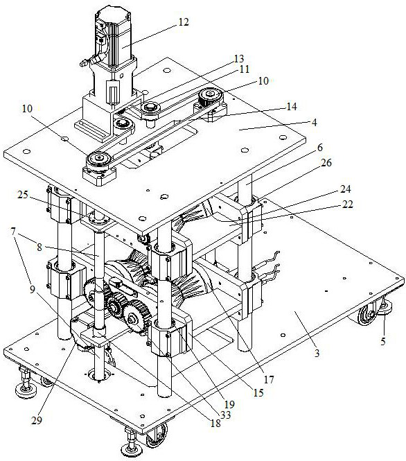
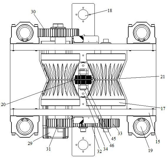
[0030] Embodiment one, see figure 1 , figure 2 , image 3 , Figure 4 and Figure 5 , a method for cutting the outer sheath of a cable, which is completed by a device for cutting the outer sheath of the cable. The device for splitting the outer sheath of the cable includes a frame on which an equipment shell 1 is arranged. The right side of the housing is provided with a feed guide port 2, and the left side is provided with a discharge port. The frame includes a bottom plate 3 and a top plate 4 . Support feet 5 are provided on the bottom plate. The base plate and the top plate are connected together by 4 vertical guide columns 6 . The four vertical guide posts are distributed in a quadrilateral shape. There are also two screw rods 7 distributed along the front and rear directions between the base plate and the base plate. The vertical guide post is parallel to the screw mandrel. The screw mandrel includes an upper section 8 and a lower section 9 . The thread direct...

Embodiment 2

[0036] Embodiment two, the difference with embodiment one is:

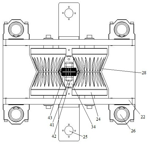
[0037] see Figure 6 , The cable outer sheath cutting device also includes a pair of cut cable outer sheath peeling mechanisms distributed along the axial direction of the lower driving roller (ie, the front-to-back direction) and located on the discharge side of the lower driving roller. The cut cable outer sheath stripping mechanism includes a pressing rod 48, a pressing rod driving cylinder 49 that drives the pressing rod to be pressed onto the cable outer sheath, and is used to block the cable core wire 50 and the cable outer sheath that are in a separated state and extend along the up and down direction. The blocking rod 52 between the sheath 51 and the blocking rod lifting cylinder 53 that drives the blocking rod lifting. The pressing end of the pressing rod is provided with a pointed end 54 . The cut cable outer sheath stripping mechanism also includes a stop bar 58 that withstands the cable protective sh...


PUM


Abstract

The invention relates to a method for cutting the outer sheath of a cable. The cable passes between an upper driving cutting assembly and a lower driving cutting assembly. The upper driving cutting assembly includes two lower driving rollers arranged in parallel and a The lower cutting blade between them, the upper driving cutting assembly includes two upper driving rollers arranged in parallel and the upper cutting blade between the two upper driving rollers; when the cable passes through, the driving mechanism drives the upper and lower driving rollers to rotate, and the upper and lower driving rollers correspond to each other one by one. Align to clamp the cable and drive the cable to translate; the upper cutting blade and the lower cutting blade are respectively cut along the cable extension direction on the upper and lower sides of the cable protective sleeve to form a cutting gap, so that the cable protective sleeve is formed into two halves; the cable The two halves of the boot are stripped from the cable core. The invention provides a device for cutting the outer sheath of a cable, which solves the laborious problem of manually stripping the sheath of the cable with a knife.

Description

technical field [0001] The invention relates to the technical field of cable construction, in particular to a method for cutting the outer sheath of a cable. Background technique [0002] The cable is composed of a cable core wire of a metal structure and a cable outer sheath of an insulating structure wrapped around the cable core wire. In the process of cable construction, it is necessary to strip the cable outer sheath at the end of the cable (some of them strip off a section of a cable, and some of them strip off the cable outer sheath on the entire cable). Because the wire stripper can only be suitable for stripping the smaller power cords of the wire diameter, and the diameter of the cable is relatively thick and cannot be stripped by the wire stripper, so the existing tool for stripping the cable sheath is a knife, namely By manually cutting the cable protective sheath with a knife and then peeling it off, there is a laborious deficiency in manual cutting. Contents...

Claims


Application Information

Patent Timeline
Patent Type & Authority Patents(China)
IPC IPC(8): H02G1/12
CPCH02G1/126H02G1/127
Inventor 袁永军方斌董涛
Owner ZHEJIANG DAYOU IND CO LTD HANGZHOU SCI TECH DEV BRANCH CO
Why Eureka
Try Eureka