
Powder metallurgy blank pressing device with automatic feeding structure

A powder metallurgy and automatic feeding technology is applied in the field of compacting devices, which can solve the problems of difficult-to-form parts removal, poor quality of formed parts, and no function of ejecting the formed parts from molds, etc., and achieves the effect of increasing quality and facilitating removal.

Active Publication Date: 2021-06-04
嘉兴市长宏铜业股份有限公司
View PDF10 Cites 0 Cited by
  • Summary
  • Abstract
  • Description
  • Claims
  • Application Information

AI Technical Summary

Problems solved by technology

[0003] Powder compaction is an unsintered blank obtained by powder compaction in the powder forming process. It is an important link in the powder metallurgy process during compaction. A compaction device is required for compaction. The existing compaction device It is impossible to realize automatic feeding during use, so that manual loading is time-consuming and laborious, and the existing compacting device does not have the function of ejecting the formed part out of the mold during use, making it difficult to take out the formed part. At the same time, the existing compacting device does not have the function of processing the burrs on the surface of the formed part, which makes the quality of the formed part poor. Therefore, we propose a powder metallurgy compacting device with an automatic feeding structure to solve this problem

Method used


Image

  • Powder metallurgy blank pressing device with automatic feeding structure
  • Powder metallurgy blank pressing device with automatic feeding structure
  • Powder metallurgy blank pressing device with automatic feeding structure

Examples


Embodiment Construction

[0022] The following will clearly and completely describe the technical solutions in the embodiments of the present invention with reference to the accompanying drawings in the embodiments of the present invention. Obviously, the described embodiments are only some, not all, embodiments of the present invention.

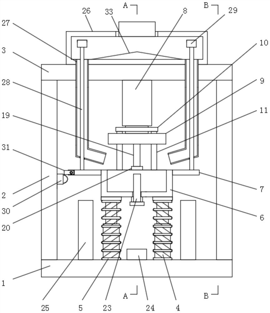
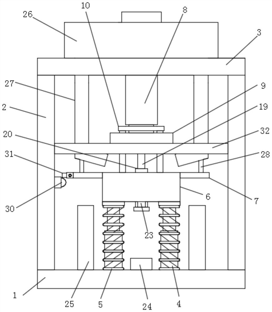
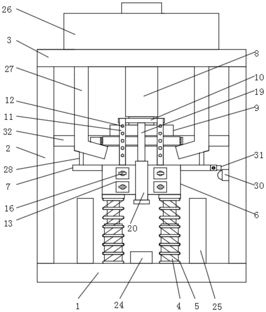
[0023] refer to Figure 1-6 , a compacting device for powder metallurgy with an automatic feeding structure, comprising a bottom plate 1, side plates 2 are fixedly installed on the left and right sides of the top of the bottom plate 1, and a top plate 3 is fixedly installed on the top of the two side plates 2, A pair of telescopic rods 4 are fixedly installed on the left and right sides of the top of the base plate 1, and the outside of the telescopic rods 4 is provided with a first spring 5. The tops of the four telescopic rods 4 are fixedly mounted with a mold 6, and the left and right sides of the mold 6 The upper part of each is fixedly equipped with a connecting...


PUM


Abstract

The invention relates to the technical field of blank pressing devices, in particular to a powder metallurgy blank pressing device with an automatic feeding structure. The powder metallurgy blank pressing device comprises a bottom plate, wherein side plates are fixedly mounted on the left side and the right side of the top end of the bottom plate respectively, a top plate is fixedly mounted at the top ends of the two side plates jointly, a pair of telescopic rods are fixedly installed on the left side and the right side of the top end of the bottom plate respectively, the telescopic rods are sleeved with first springs, a mold is fixedly installed at the top ends of the four telescopic rods jointly, and connecting plates are fixedly installed on the upper portions of the left side and the right side of the mold respectively. The powder metallurgy blank pressing device can implement automatic feeding and stop feeding in the mold, manual feeding is not needed, time and labor are saved, a formed part can be automatically ejected out so that the formed part can be conveniently taken out, meanwhile, a switch can be touched to start a grinding mechanism during ejection so that burrs on the surface of the formed part can be ground, the quality of the formed part can be improved after the burrs are removed, and the device is worthy of application and popularization.

Description

technical field [0001] The invention relates to the technical field of compacting devices, in particular to a compacting device for powder metallurgy with an automatic feeding structure. Background technique [0002] Powder metallurgy is a process technology for producing metal powder or using metal powder (or a mixture of metal powder and non-metal powder) as raw material, forming and sintering to manufacture metal materials, composite materials and various types of products. The powder metallurgy method has similarities with the production of ceramics, and both belong to the powder sintering technology. Therefore, a series of new powder metallurgy technologies can also be used for the preparation of ceramic materials. [0003] Powder compaction is an unsintered blank obtained by powder compaction in the powder forming process. It is an important link in the powder metallurgy process during compaction. A compaction device is required for compaction. The existing compaction ...

Claims


Application Information

Patent Timeline
Patent Type & Authority Applications(China)
IPC IPC(8): B22F3/00B22F3/03B24B9/04B24B41/00
CPCB22F3/004B22F3/005B22F3/03B24B9/04B24B41/005Y02P10/25
Inventor 陶青芳
Owner 嘉兴市长宏铜业股份有限公司
Learn More