Automobile seat shock absorber and automobile seat

A technology for car seats and shock absorbers, which is applied to vehicle seats, seat suspension devices, seat heating/ventilation devices, etc. question

Active Publication Date: 2020-06-12
盐城大丰盛源机械有限责任公司
View PDF12 Cites 2 Cited by
  • Summary
  • Abstract
  • Description
  • Claims
  • Application Information

AI Technical Summary

Problems solved by technology

[0005] The object of the present invention is to provide a car seat shock absorber and a car seat, aiming to solve the following problem: the slide plate of the existing car seat shock absorber hits the car seat during the shock-absorbing movement process The inner wall of the shock absorber also causes a large vibration to the shock absorber body of the car seat, which ultimately affects the comfort of the car seat

Method used


Image

  • Automobile seat shock absorber and automobile seat
  • Automobile seat shock absorber and automobile seat

Examples


Embodiment 1

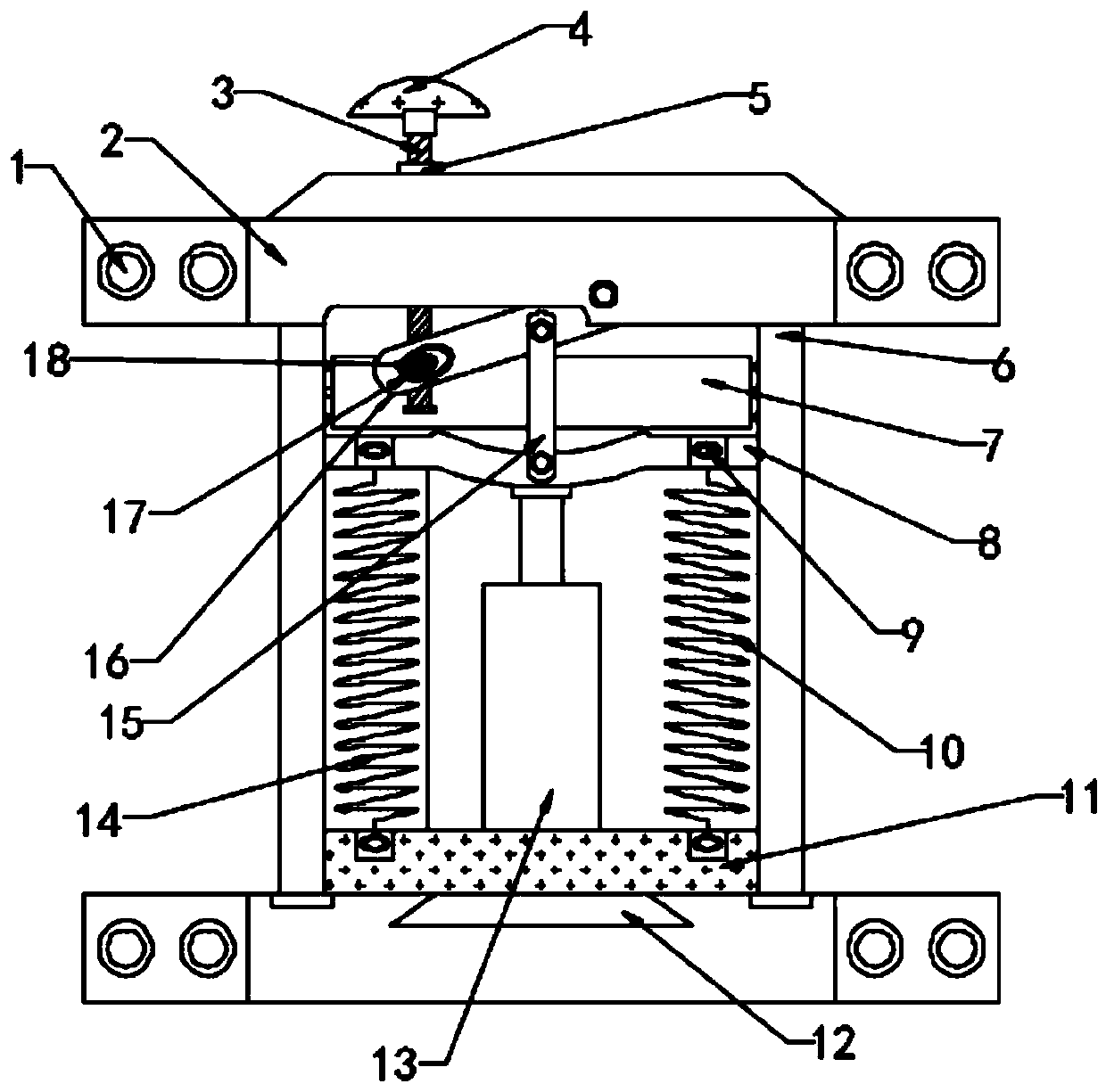
[0017] See figure 1 with figure 2 , A car seat shock absorber provided in Embodiment 1 of the present invention, the car seat shock absorber includes: a shock absorber body 2, two sides of the shock absorber body 2 are provided with sliding rails 6, two sliding A buffer assembly is arranged between the rails 6, a sliding piece 8 is slidably installed inside the sliding rail 6, and the sliding piece 8 is connected with the buffer assembly;

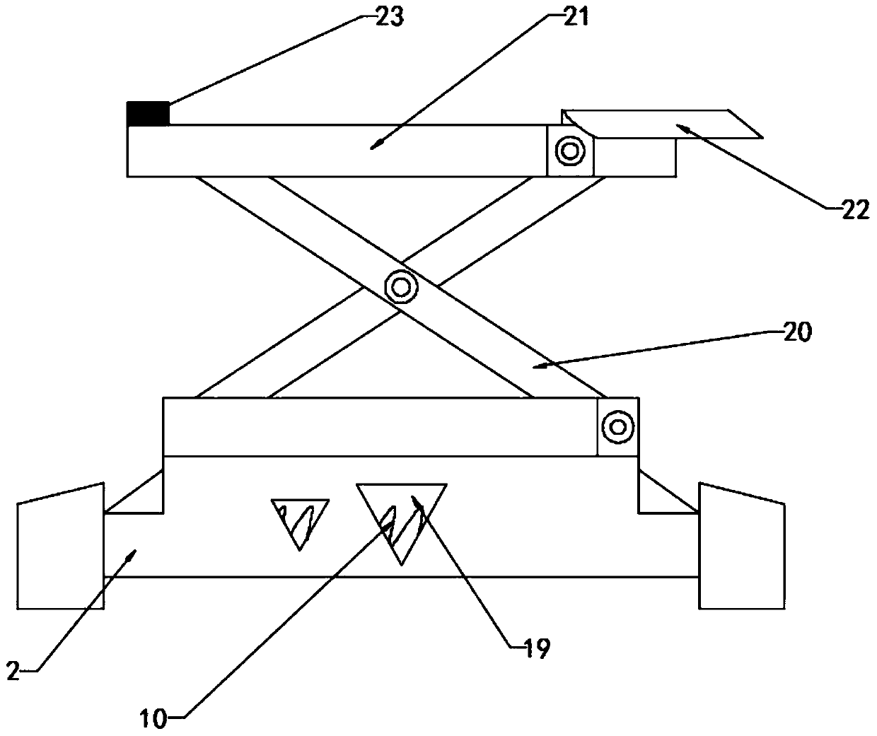
[0018] The upper end of the sliding sheet 8 is provided with a bracket 20, the number of brackets 20 is four, the two brackets 20 on the side constitute a group, and the two brackets 20 in a group are movably connected by a pin hinge; One end of one of the brackets 20 is hinged and movably mounted on the shock absorber body 2, and one end of the other bracket 20 in the group is installed and fixed on the sliding plate 8 through the second mounting hole 9 by bolts; two brackets 20 in the group A pallet 21 is installed at the upper end;

[0019...

Embodiment 2

[0023] In the second embodiment of the present invention, a buffer assembly is provided. The buffer assembly includes a first buffer member and a second buffer member. The first buffer member and the second buffer member are distributed on the sliding sheet 8 between the sliding rails 6 Front and back

[0024] Further, the first buffer member includes a damper 13 and a compression spring. One end of the damper 13 is connected and fixed with the sliding plate 8, the other end of the damper 13 is connected and fixed with a fixed block 11, and the fixed block 11 is installed and fixed on the shock absorber body. 2 on; one end of the compression spring is connected and fixed with the sliding plate 8, and the other end of the compression spring is connected and fixed with the sliding plate 8;

[0025] Specifically, the number of the compression springs is two, namely, the first compression spring 10 and the second compression spring 14. The first compression spring 10 and the second com...


PUM


Abstract

The invention relates to the field of automobile equipment, in particular to an automobile seat shock absorber and an automobile seat. The automobile seat shock absorber comprises a shock absorber body, sliding rails are arranged on the two sides of the shock absorber body, a buffer assembly is arranged between the two sliding rails, and sliding pieces are installed in the sliding rails in a sliding mode and connected with the buffer assembly. According to the automobile seat shock absorber, through the cooperation effect of two compression springs of a first buffer piece of the buffer assembly and a damper, the automobile seat installed on the automobile seat shock absorber can be buffered and damped for the first time; a sliding block of a second buffering piece of the buffering assemblycan play a secondary fixing role on the sliding sheet, and the moving sliding sheet does not directly impact the interior of the shock absorber body for speed reduction, so that a certain buffering and shock absorption effect is also achieved; and, in addition, the screw rod is driven to adjust the distance of the sliding block by rotating the rotating handle, and finally the distance of the sliding block can be reasonably adjusted according to installation requirements of the automobile seat cushion plate.

Description

Technical field [0001] The invention relates to the field of automobile equipment, in particular to a car seat shock absorber and a car seat. Background technique [0002] The car seat shock absorber uses elastic elements (metal springs or airbags), dampers, frames and other structures to form a shock absorption system to improve the seat's absorption of vibration, improve the smoothness of the driving process, and thereby increase the comfort of the seat. [0003] The car seat shock absorber in the prior art has the following shortcomings. The damper directly supports the sliding piece and directly contacts the inner wall of the car seat shock absorber. During the damping movement of the sliding piece, the sliding piece hits the shock absorption of the car seat The inner wall of the car seat also causes greater vibration to the car seat shock absorber body, which ultimately affects the comfort of the car seat. [0004] In view of the above-mentioned problems in the background art, ...

Claims


Application Information

Patent Timeline
Patent Type & Authority Applications(China)
IPC IPC(8): B60N2/50B60N2/54B60N2/56
CPCB60N2/50B60N2/54B60N2/5621
Inventor 刘丽娜
Owner 盐城大丰盛源机械有限责任公司
Why Eureka
Try Eureka