
A connection structure between torsion bar and rocker arm of rolling stock anti-rolling torsion bar device

A technology of anti-roll torsion bar and connection structure, which is applied in the direction of lateral relative movement between the chassis and the bogie, transportation and packaging, railway car body parts, etc. Assembly, low connection strength and other problems, to achieve the effect of improving anti-rolling performance

Active Publication Date: 2020-12-01
日照吉安达机电有限公司
View PDF10 Cites 0 Cited by
  • Summary
  • Abstract
  • Description
  • Claims
  • Application Information

AI Technical Summary

Problems solved by technology

[0004] At present, the torsion bar and the rocker arm adopt a spline connection structure. In this structure, in the state of rolling motion, the force-bearing part is only the partial spline tooth surface, so the contact between the tooth surface and the tooth surface belongs to the line contact motion pair, and the connection strength is lower than that of the surface. The contact connection structure, and the spline has strict requirements on the angle, so it is difficult to realize the assembly

Method used


Image

  • A connection structure between torsion bar and rocker arm of rolling stock anti-rolling torsion bar device
  • A connection structure between torsion bar and rocker arm of rolling stock anti-rolling torsion bar device
  • A connection structure between torsion bar and rocker arm of rolling stock anti-rolling torsion bar device

Examples


Embodiment

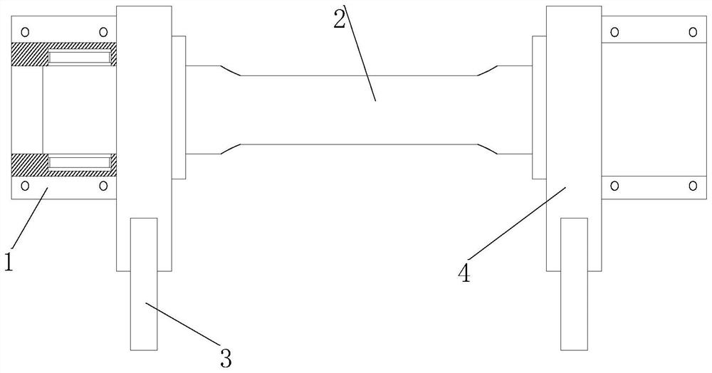
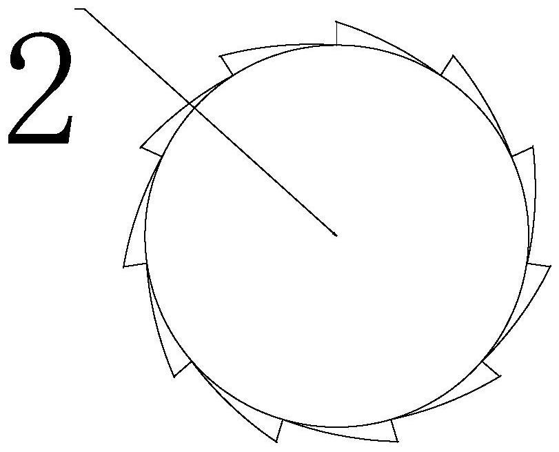
[0030] Example: such as Figure 1-8 As shown, a locomotive anti-rolling torsion bar device torsion bar and rocker arm connection structure, the connection structure includes a bracket 1, a torsion bar 2, a rocker arm 3, a docking device 4, and the torsion bar 2 is arranged sequentially from the middle to both ends The limit snap ring 5, the docking device 4, the bracket 1, the inside of the bracket 1 is provided with a bearing, the torsion bar 2 is installed on the bracket 1 through the rotation of the bearing, the side wall of the docking device 4 and the bracket 1 is fixed by screws, and the limit snap ring 5 is installed on the other side of the docking device 4, and the limit snap ring 5 plays a role in limiting the position of the docking device 4. There are two sets of level adjustment mechanisms 4-1 inside the docking device 4, and one end of the docking device 4 is set on the On the torsion bar 2 , the other end of the docking device 4 is rotatably connected to the roc...


PUM


Abstract

The invention discloses a connection structure between a torsion bar and a rocker arm of an anti-rolling torsion bar device for a locomotive and vehicle. The connection structure includes a bracket, a torsion bar, a rocker arm, and a docking device. Snap ring, docking device, bracket, the docking device is fixed with the bracket, two sets of level adjustment mechanisms are arranged on the docking device, and rocker arms are arranged on the docking device, and the two sets of level adjustment mechanisms swing the rocker arms up (down) The force of the torsion bar is amplified and acts on the torsion bar. The invention is scientific and reasonable, and is safe and convenient to use. The docking device will only generate two sets of opposite forces on the torsion bar, and the force of the rocker arm's up (down) swing can be amplified by the level adjustment mechanism. And act on the torsion bar, the torsion bar is torsional deformation under the action of opposite forces at both ends, and the torsional deformation of the torsion bar is increased by the amplified force, so as to obtain a large elastic counter moment to resist the roll of the vehicle, thereby improving Rolling resistance of the vehicle.

Description

technical field [0001] The invention relates to the technical field of a connection structure between a torsion bar and a rocker arm, in particular to a connection structure between a torsion bar and a rocker arm of an anti-rolling torsion bar device for a rolling stock. Background technique [0002] With the development of high-speed trains and urban rail vehicles, air springs are being used more and more. After the secondary suspension adopts air springs with large deflection, better vertical performance of the vehicle is obtained, but it also brings a relatively large The problem is that the roll stiffness of the vehicle is reduced. [0003] Due to the reduction of vehicle roll stiffness, the vehicle's flexibility coefficient and roll angle will increase significantly, which not only affects the stability of the vehicle, but also brings serious safety hazards. In order to solve this problem, in order to suppress the vehicle's anti-roll To reduce the stiffness, the vehicl...

Claims


Application Information

Patent Timeline
Patent Type & Authority Patents(China)
IPC IPC(8): B61F5/24
CPCB61F5/24B61F5/50
Inventor 郑家旗
Owner 日照吉安达机电有限公司
Learn More