Hydraulic jack with high jacking force

A jack and lift technology, which is applied in the field of hydraulic jacks, can solve the problems of limit seat wear, accelerate deformation and damage speed, reduce the limit effect, etc., and achieve the effect of compact and stable structural connection, avoiding displacement deviation, and avoiding damage and deformation

Pending Publication Date: 2020-06-12
江苏海力达机电制造有限公司
View PDF0 Cites 0 Cited by
  • Summary
  • Abstract
  • Description
  • Claims
  • Application Information

AI Technical Summary

Problems solved by technology

However, the existing limit mechanism welds the limit seat on the side plate or the back plate of the handle seat, the limit seat on the side plate of the handle seat and the corresponding support plate are mutually fitted to limit the position, and the limit seat on the back plate of the handle seat The rod between the position seat and the two support plates is used to limit the position. When welding the limit seat, welding stress will be generated on the side plate or back plate of the handle seat. When the position limit seat and the support plate or the sleeve rod are within the unit swing stroke During the limit process, it is inevitable that there will be contact and impact with the support plate or the sleeve rod. For the side plate or back plate that has already generated welding stress inside, the deformation and damage speed will be further accelerated. The service life of the handle seat is limited by the engagement of the limit seat and the support plate or the back plate, which is very easy to cause wear on the joint of the limit seat. After long-term wear, the swing stroke distance of the handle seat cannot be guaranteed to be constant. resistance, also reduces the limiter effect

Method used


Image

  • Hydraulic jack with high jacking force
  • Hydraulic jack with high jacking force
  • Hydraulic jack with high jacking force

Examples


Embodiment approach

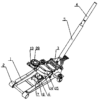
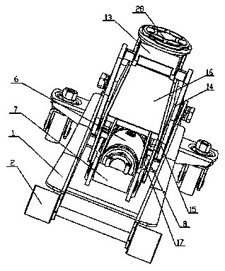
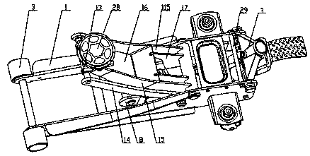
[0046] Such as Figure 1 to Figure 4 It shows an embodiment of an oil hydraulic jack with high lifting force of the present invention, including

[0047] A base mechanism, the base mechanism includes a base composed of two upwardly extending support plates 1, with rollers 2 on the base;

[0048] A handle bar mechanism; the handle bar mechanism includes a handle seat 3 placed between two support plates 1 and a first handle bar 4 and a second handle bar 5 placed on the handle seat 3 and connected to each other;

[0049] A driving mechanism, the driving mechanism includes a hydraulic cylinder 6 arranged on the two support plates, and the hydraulic cylinder 6 is arranged horizontally;

[0050] A lifting mechanism; the lifting mechanism includes a base, a limit shaft group and a lifting seat, the base includes a fixed column 7 placed between two support plates 1, and the extension direction of the fixed column 7 is perpendicular to the extension direction of the support plate 1 ,...


PUM


Abstract

The invention relates to a hydraulic jack with high jacking force. The hydraulic jack comprises a base mechanism, a handle lever mechanism, a driving mechanism and a lifting mechanism. The base mechanism comprises a base composed of two upwards extending supporting plates, and wheels are arranged on the base. The lifting mechanism comprises a base, a limiting shaft set and a lifting seat. The basecomprises a fixing pillar arranged between the two supporting plates, and pull rods are connected to the two ends of the fixing pillar correspondingly. The limiting shaft set comprises a limiting shaft rod penetrating the two supporting plates, and the part, located between the two supporting plates, of the limiting shaft rod is sleeved with a shaft sleeve. The lifting seat comprises an ejectinghead, the side end of the ejecting head is movably connected with an outer side plate and an inner side plate, a rib plate is arranged between inner side plates of the two side ends of the ejecting head, and strengthening plates are connected to the two sides of the rib plate. Clearances are formed between the pull rods and the strengthening plates, and clearances are formed between the pull rodsand the inner side plates. Guide slopes are arranged on the end faces of the two sides of pull rod shafts. The hydraulic jack with the high jacking force has the following beneficial effects that thehigh jacking force and the high jacking stroke are achieved, and the structural strength of the lifting mechanism and a handle seat is ensured.

Description

Technical field: [0001] The invention belongs to the field of hydraulic jacks, and in particular relates to a hydraulic jack with high lifting force. Background technique: [0002] The hydraulic jack is a light and small lifting device that drives the lifting mechanism to lift heavy objects within the stroke through the hydraulic cylinder. It is used in factories, mines, transportation and other departments for vehicle maintenance and other lifting and supporting work. There are following defects in existing hydraulic jacks: [0003] 1. The lifting mechanism is directly tilted to drive the lifting mechanism through the hydraulic cylinder, so that the lifting mechanism swings around the shaft in the support plate, and the hydraulic cylinder directly drives the lifting mechanism to generate thrust for the lifting mechanism, while the weight above the lifting mechanism The pressure generated by the hydraulic cylinder greatly offsets the jacking force of the hydraulic cylinder....

Claims


Application Information

Patent Timeline
IPC IPC(8): B66F3/24B66F3/25
CPCB66F3/24B66F3/25B66F2700/05Y02B50/00
Inventor 傅勇刚田承裘
Owner 江苏海力达机电制造有限公司
Why Eureka
Try Eureka