Water shedding device for umbrellas

A technology for throwing water and umbrellas, which is applied to household cleaning devices, types of drying products, lighting and heating equipment, etc., can solve the problems of waste, large flow of people, throwing off, etc., and achieve the effect of good water removal and convenient use.

Inactive Publication Date: 2020-06-12
南京溧水高新产业股权投资有限公司
View PDF5 Cites 6 Cited by
  • Summary
  • Abstract
  • Description
  • Claims
  • Application Information

AI Technical Summary

Problems solved by technology

[0003] 1. It is difficult to completely shake off the water on the umbrella by shaking the umbrella manually, only part of the water droplets will be thrown off, so the water removal effect is not ideal. After entering the room, the water on the umbrella will still drip onto the ground ;
[0004] 2. Cover the umbrella with a plastic bag. Although it can prevent the water dropl

Method used


Image

  • Water shedding device for umbrellas
  • Water shedding device for umbrellas
  • Water shedding device for umbrellas

Examples


Embodiment 1

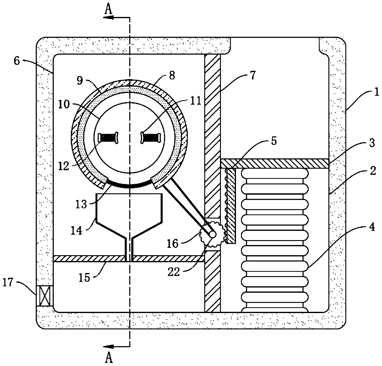
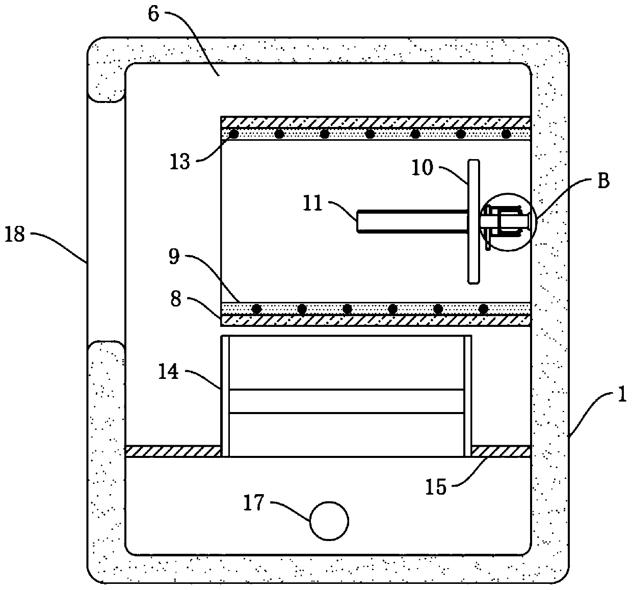
[0026] refer to Figure 1-3 , an umbrella water throwing device, comprising a housing 1, the inner wall of the housing 1 is fixedly connected with a partition 7, the partition 7 divides the inside of the housing 1 into an operation chamber 6 on the left side and a control chamber 2 on the right side, the control chamber 2. The upper wall is provided with a communication port, and the side wall of the operation chamber 6 is provided with a placement port 18, from which the umbrella can be put into the device.

[0027] The operating chamber 6 is provided with an operating mechanism and a water storage mechanism. The operating mechanism includes a mounting plate 8, which is fixedly connected to the inner wall of the operating chamber 6. The mounting plate 8 is ring-shaped, and the lower end of the mounting plate 8 is provided with a gap. The mounting plate 8 The side wall is provided with a water-absorbing sponge 9, and the inner wall of the operation chamber 6 is connected with ...

Embodiment 2

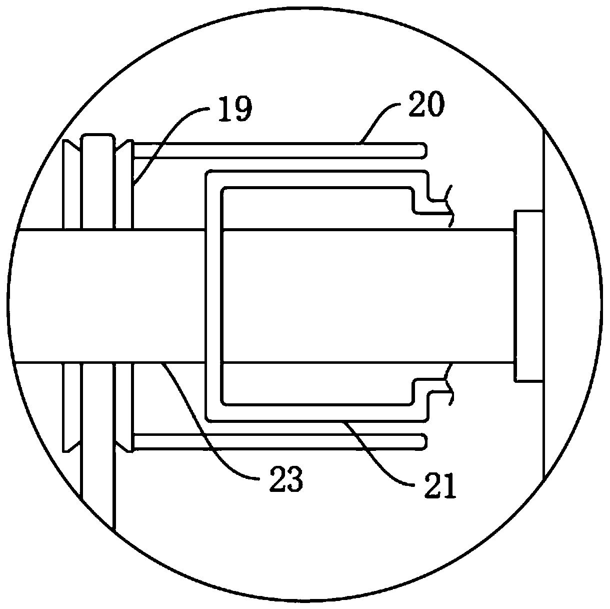
[0036] refer to Figure 4, a water throwing device for an umbrella, the upper wall of the lifting plate 3 is provided with a plurality of capillary tubes 24, and the plurality of capillary tubes 24 communicate with the side wall of the water receiving bucket 14 through the connecting pipe 25.

[0037] In this embodiment, when the user walks on a rainy day, the soles of the shoes will be stained with a large amount of rainwater. When people step on the lifting plate 3, when the soles are in contact with the capillary tubes 24 on the side walls of the lifting plate 3, according to the capillary phenomenon, the capillary tubes 24 can hold the soles The water inhaled in the connecting pipe 25 flows into the water receiving bucket 14, and finally flows to the lower end of the water retaining plate 15. Compared with Embodiment 1, this embodiment can remove the water from the soles of people's shoes while water is thrown from the umbrella. Absorption prevents people from falling on s...


PUM


Abstract

The invention discloses a water shedding device for umbrellas. The water shedding device comprises a shell, wherein the inner walls of the shell are fixedly connected to a baffle plate; the interior of the shell is divided into a left operating cavity and a right control cavity by the baffle plate; a connection opening is formed in the upper wall of the control cavity; a placement opening is formed in the side wall of the operating cavity; a control mechanism is arranged inside the control cavity; an operating mechanism and a water storage mechanism are arranged inside the operating cavity; the operating mechanism comprises a mounting plate which is fixedly connected to the inner wall of the operating cavity; a water-absorbing sponge is arranged on the side wall of the mounting plate; theinner wall of the operating cavity is rotatably connected to a placement plate through a first rotating shaft; the placement plate is provided with a clamping part; and a water squeezing mechanism isarranged in the operating cavity. The water shedding device can quickly shed water on the umbrellas without using plastic bags, does not cause wasting, and can also prevent water on shoe soles from being stained onto the ground to make the ground slippery and cause people to slip.

Description

technical field [0001] The invention relates to the technical field of umbrella water removal equipment, in particular to an umbrella water removal device. Background technique [0002] On rainy days, before people enter some large shopping malls or some office buildings, if the water on the umbrellas cannot be disposed of, it will drip on the indoor ground. Moreover, the floor tiles in these shopping malls and office buildings are very smooth, and a large number of The water droplets falling on the floor tiles are easy to cause people to fall because the ground is too slippery. Therefore, people generally shake the umbrella manually to shake off the water on the umbrella before entering it, or use a plastic bag to cover the umbrella, Enter indoor, however, all there is following problem in these two kinds of ways: [0003] 1. It is difficult to completely shake off the water on the umbrella by shaking the umbrella manually, only part of the water droplets will be thrown of...

Claims


Application Information

Patent Timeline
IPC IPC(8): F26B5/08F26B5/14F26B5/16F26B11/18F26B25/00F26B25/02F26B25/18A47L23/20
CPCA47L23/20F26B5/08F26B5/14F26B5/16F26B11/18F26B25/003F26B25/02F26B25/185F26B2210/10
Inventor 吴小花张洋洋
Owner 南京溧水高新产业股权投资有限公司
Why Eureka
Try Eureka