A ground reinforcement method

A foundation reinforcement and pre-reinforcement technology, which is applied in infrastructure engineering, construction, soil protection, etc., can solve the problems of waste of working hours, affecting the progress of the construction period, and low efficiency

Active Publication Date: 2021-11-16
ANHUI SANLIAN UNIV
View PDF6 Cites 0 Cited by
  • Summary
  • Abstract
  • Description
  • Claims
  • Application Information

AI Technical Summary

Problems solved by technology

[0003] The current foundation reinforcement method mainly uses dynamic tamping machines to tamp the foundation, but when the existing dynamic tamping machines tamp the foundation with high water content, the efficiency is low, and the phenomenon of waste of working hours is serious, which affects the entire construction period.

Method used


Image

  • A ground reinforcement method

Examples


Embodiment 1

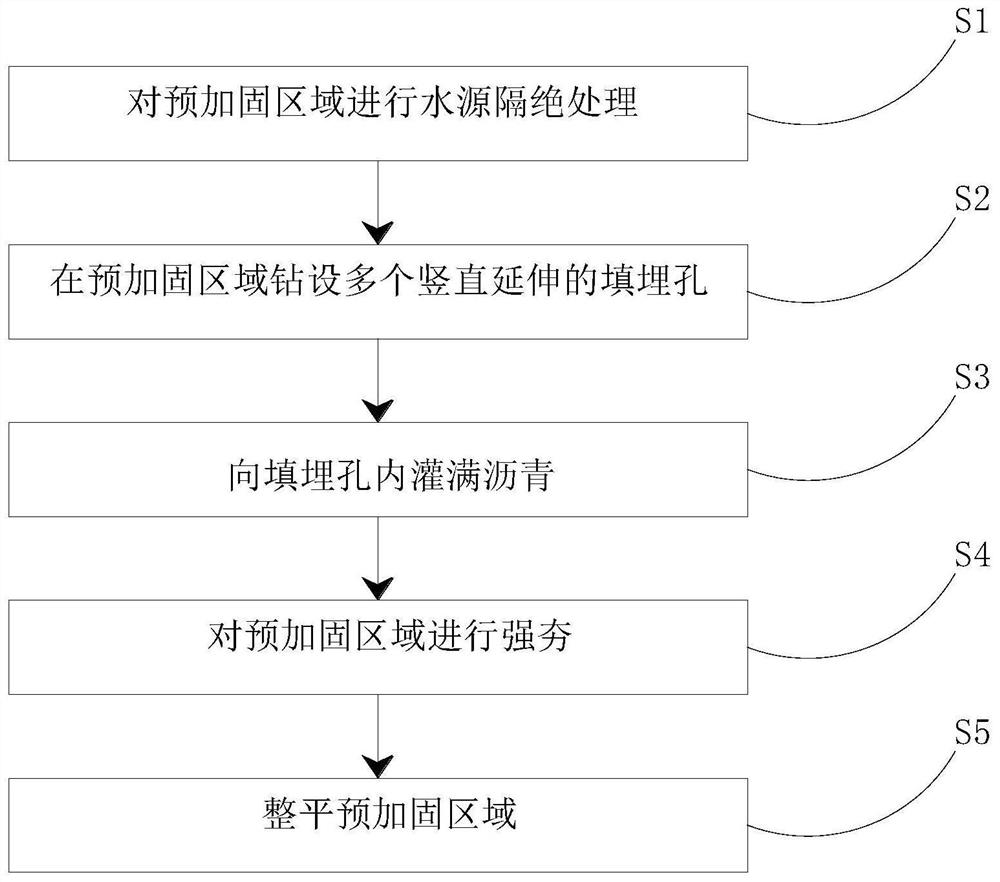
[0034] A ground reinforcement method, comprising the steps of:

[0035] S1. Carry out water source isolation treatment on the pre-reinforcement area, specifically including the following steps:

[0036] S11. Dig a water blocking ditch with a depth of 0.8m around the pre-reinforcement area, and fill the water blocking ditch with sand;

[0037] S12. Excavating multiple crisscross water storage ditches with a depth of 0.3m in the pre-reinforcement area;

[0038] S2. Drill multiple burial holes with a depth of 1.55m in rows and columns on the surface of the pre-reinforcement area at a distance of 1×1m;

[0039] S3, fill the asphalt in the landfill hole, specifically include the following steps:

[0040] S31, evenly laying a layer of activated carbon powder with a thickness of 0.5mm on the hole wall of the buried hole;

[0041] S32, pouring asphalt with a temperature of 75°C into the landfill hole;

[0042] S33. Vertically insert the tapered steel column into the asphalt and ex...

Embodiment 2

[0047] A ground reinforcement method, comprising the steps of:

[0048] S1. Carry out water source isolation treatment on the pre-reinforcement area, specifically including the following steps:

[0049] S11. Dig a water blocking ditch with a depth of 0.5m around the pre-reinforcement area, and fill the water blocking ditch with sand;

[0050] S12. Digging and setting multiple criss-crossing water storage ditches with a depth of 0.4m in the pre-reinforcement area;

[0051] S2. Drill multiple burial holes with a depth of 1.7m in rows and columns on the surface of the pre-reinforcement area at a distance of 1×1m;

[0052] S3, fill the asphalt in the landfill hole, specifically include the following steps:

[0053] S31, evenly laying a layer of activated carbon powder with a thickness of 0.5mm on the hole wall of the buried hole;

[0054] S32, pouring asphalt with a temperature of 70°C into the landfill hole;

[0055] S33. Vertically insert the tapered steel column into the as...

Embodiment 3

[0060] A ground reinforcement method, comprising the steps of:

[0061] S1. Carry out water source isolation treatment on the pre-reinforcement area, specifically including the following steps:

[0062] S11. Dig a water blocking ditch with a depth of 0.7m around the pre-reinforcement area, and fill the water blocking ditch with sand;

[0063] S12. Excavating multiple crisscross water storage ditches with a depth of 0.5m in the pre-reinforcement area;

[0064] S2. Drill multiple burial holes with a depth of 1.5m in rows and columns on the surface of the pre-reinforcement area at a distance of 1×1m;

[0065] S3, fill the asphalt in the landfill hole, specifically include the following steps:

[0066]S31, evenly laying a layer of activated carbon powder with a thickness of 0.5mm on the hole wall of the buried hole;

[0067] S32, pouring asphalt with a temperature of 72°C into the landfill hole;

[0068] S33. Vertically insert the tapered steel column into the asphalt and exte...


PUM


Abstract

The present invention proposes a foundation reinforcement method, comprising the following steps: S1, performing water source isolation treatment on the pre-reinforcement area; S2, drilling a plurality of vertically extending landfill holes in the pre-reinforcement area; Filling with asphalt; S4, performing dynamic compaction on the pre-reinforcement area; S5, leveling the pre-reinforcement area. The invention prevents the external water source from infiltrating into the foundation and causing the foundation to be soft by isolating the water source of the foundation; opening a landfill hole in the foundation and pouring asphalt, and the asphalt has plasticity after cooling, which can make the foundation soil have certain ductility.

Description

technical field [0001] The invention relates to the technical field of roadbed engineering, in particular to a foundation reinforcement method. Background technique [0002] During building construction, it is necessary to ensure that the foundation has sufficient bearing capacity, especially when constructing in coastal areas, because the foundation in coastal areas is generally soft ground, with high water content, poor permeability, and low bearing capacity, in order to ensure construction quality and avoid foundation collapse Subsidence, cracks and other problems caused by the need for reinforcement of the foundation. [0003] The current foundation reinforcement method mainly uses a dynamic tamping machine to tamp the foundation. However, when the existing dynamic tamping machine tamps the foundation with high water content, the efficiency is low, and the waste of working hours is serious, which affects the entire construction period. Contents of the invention [000...

Claims


Application Information

Patent Timeline
Patent Type & Authority Patents(China)
IPC IPC(8): E02D3/08E02D3/10E02D3/11E02D3/12
CPCE02D3/08E02D3/10E02D3/11E02D3/123
Inventor 王冰玲许倩倩沉文欣
Owner ANHUI SANLIAN UNIV
Why Eureka
Try Eureka