
Wear resistance detection device for warp knitting cloth

A detection device and wear resistance technology, which is applied in the field of warp knitted fabric detection, can solve the problems of narrow application range and achieve the effect of expanding the application range

Inactive Publication Date: 2020-06-12
泉州陶纪塑胶有限公司
View PDF0 Cites 1 Cited by
  • Summary
  • Abstract
  • Description
  • Claims
  • Application Information

AI Technical Summary

Problems solved by technology

Existing wear resistance testing devices require warp-knitted fabrics of a specific size when used in practice. When testing large-area warp-knitted fabrics, they need to be cut to a specific size first, and the scope of application is narrow.

Method used


Image

  • Wear resistance detection device for warp knitting cloth
  • Wear resistance detection device for warp knitting cloth
  • Wear resistance detection device for warp knitting cloth

Examples


Embodiment 1

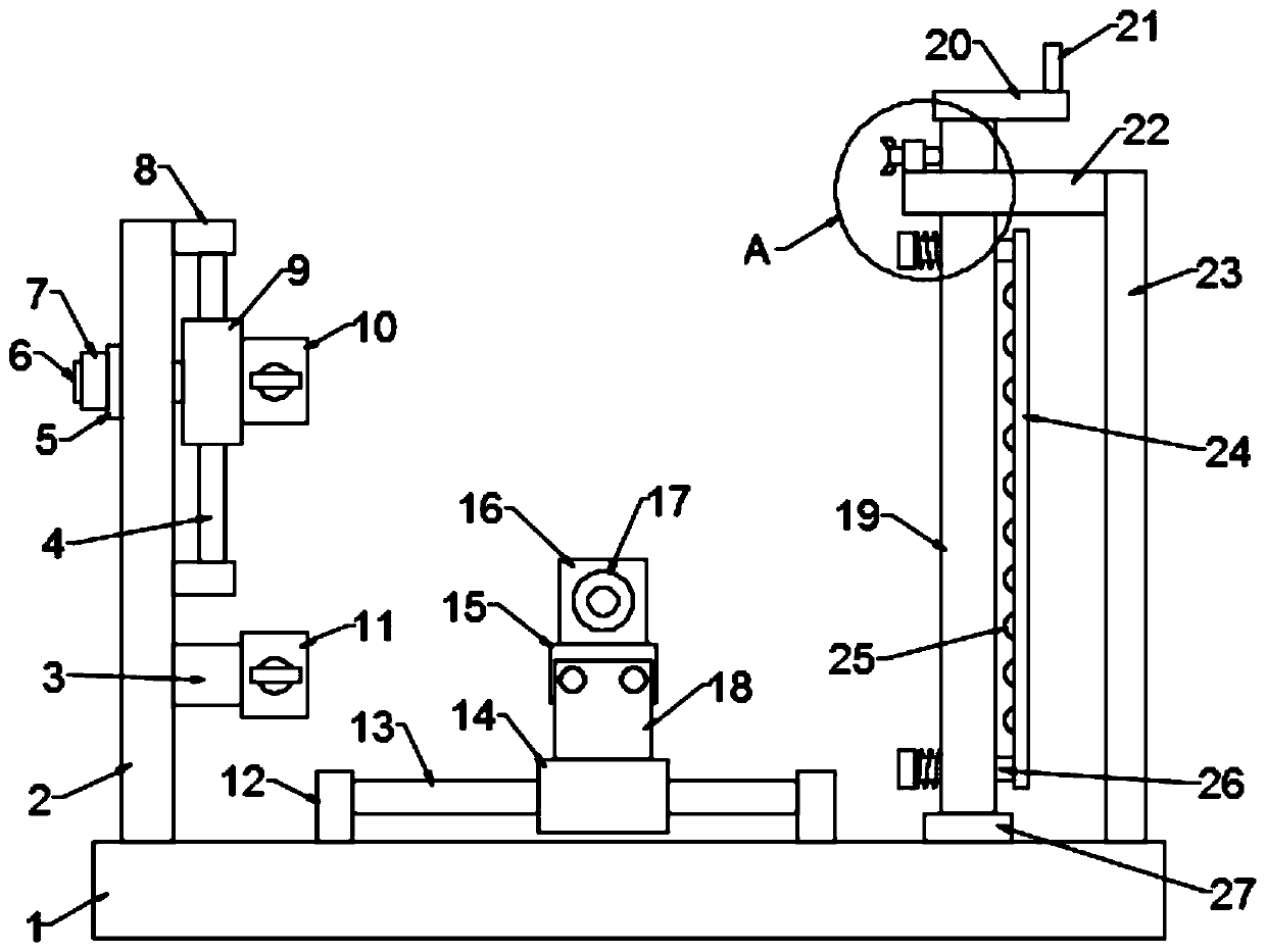
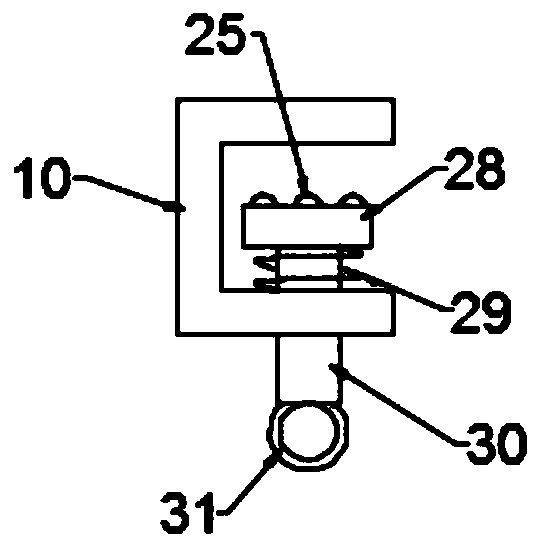
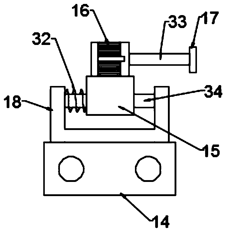
[0030] see Figure 1-5 , in the embodiment of the present invention, a kind of wear resistance detection device of warp knitted cloth comprises base plate 1 and motor 16, and the output shaft of motor 16 is connected with rotating shaft 33, and grinding disc 17 is installed on rotating shaft 33; A vertical plate 2 and a column 23 are fixed, a fixed block 3 is fixed on the vertical plate 2, a second U-shaped seat 11 is installed on the fixed block 3, and a first U-shaped seat 10 is provided on the upper side of the second U-shaped seat 11, Both the first U-shaped seat 10 and the second U-shaped seat 11 are slidably provided with a fourth slide bar 30, and the two ends of the fourth slide bar 30 are respectively connected with a pull ring 31 and a pressure block 28, and on the fourth slide bar 30 The first spring 29 is sleeved, and the vertical plate 2 is provided with an adjustment assembly for adjusting the height of the first U-shaped seat 10;

[0031] The top of the column ...

Embodiment 2

[0043] see Figure 6 , in the embodiment of the present invention, a warp knitted cloth wear resistance detection device is different from embodiment 1 in that an inner rod 40 and an outer cylinder 42 are provided between the mounting seat 18 and the slider 14, and the inner rod 40 is slidably connected with the inner wall of the outer cylinder 42, and the locking bolt 41 for locking the inner rod 40 is threadedly installed on the outer cylinder 42; through the sliding fit between the inner rod 40 and the outer cylinder 42, the mounting seat 18 can be raised and lowered to make the grinding disc 17 At different heights, it is possible to inspect areas of different heights on the warp knitted fabric.


PUM


Abstract

The present invention is suitable for the technical field of warp knitting cloth detection, and provides a wear resistance detection device for warp knitting cloth. The device comprises a bottom plateand a motor, a vertical plate and a stand column are fixed to the bottom plate, a fixing block is fixed to the vertical plate, a second U-shaped base is installed on the fixing block, a first U-shaped base is arranged on the upper side of the second U-shaped base, fourth sliding rods are slidably arranged on the first U-shaped base and the second U-shaped base, and an adjusting assembly used foradjusting the height of the first U-shaped base is arranged on the vertical plate; and a winding assembly used for winding warp knitting cloth is arranged on the cross beam, and an installation assembly used for installing a motor is further arranged on the bottom plate. According to the wear resistance detection device for the warp knitting cloth, the height of the first U-shaped base is adjusted, and then the distance between the first U-shaped base and the second U-shaped base is adjusted, so that the warp knitting cloth with different heights is fixed; the rotating rod is rotated through the handle, the warp knitting cloth is wound till the warp knitting cloth is in a tensioned state, the device is suitable for warp knitting cloth of different lengths, and the application range is enlarged.

Description

technical field [0001] The invention belongs to the technical field of warp knitted fabric detection, in particular to a wear resistance detection device of warp knitted fabric. Background technique [0002] The abrasion resistance test of warp knitted fabric is an important index to test the quality of warp knitted fabric. Existing wear resistance detection devices require warp knitted fabrics of a specific size in actual use. When testing warp knitted fabrics with a large area, they need to be cut into specific sizes first, and the scope of application is narrow. In view of the above problems, the present invention proposes a wear resistance detection device for warp knitted fabrics. Contents of the invention [0003] The object of the present invention is to provide a warp-knitted fabric wear resistance testing device to solve the problems raised in the above-mentioned background technology. [0004] To achieve the above object, the present invention provides the foll...

Claims


Application Information

Patent Timeline
Patent Type & Authority Applications(China)
IPC IPC(8): G01N3/56G01N3/04G01N3/02
CPCG01N3/02G01N3/04G01N3/56G01N2203/0282G01N2203/0423
Inventor 赵振
Owner 泉州陶纪塑胶有限公司
Learn More