
Transmission Line Test Set

A test device and transmission line technology, applied in the direction of coupling devices, parts of connecting devices, electrical components, etc., can solve problems such as difficult problems and increasingly high requirements for alignment accuracy

Active Publication Date: 2021-06-11
AAC PRECISE MFG TECH CHANGZHOU
View PDF0 Cites 0 Cited by
  • Summary
  • Abstract
  • Description
  • Claims
  • Application Information

AI Technical Summary

Problems solved by technology

[0007] The purpose of the present invention is to provide a transmission line testing device to solve the problem of increasingly high accuracy requirements for the alignment accuracy of the test probes of the test fixture and the connector due to the miniaturization of the used connectors. Problems where the counterpoint method becomes very difficult

Method used


Image

  • Transmission Line Test Set
  • Transmission Line Test Set
  • Transmission Line Test Set

Examples


Embodiment Construction

[0029] The present invention will be further described below in conjunction with the accompanying drawings and embodiments.

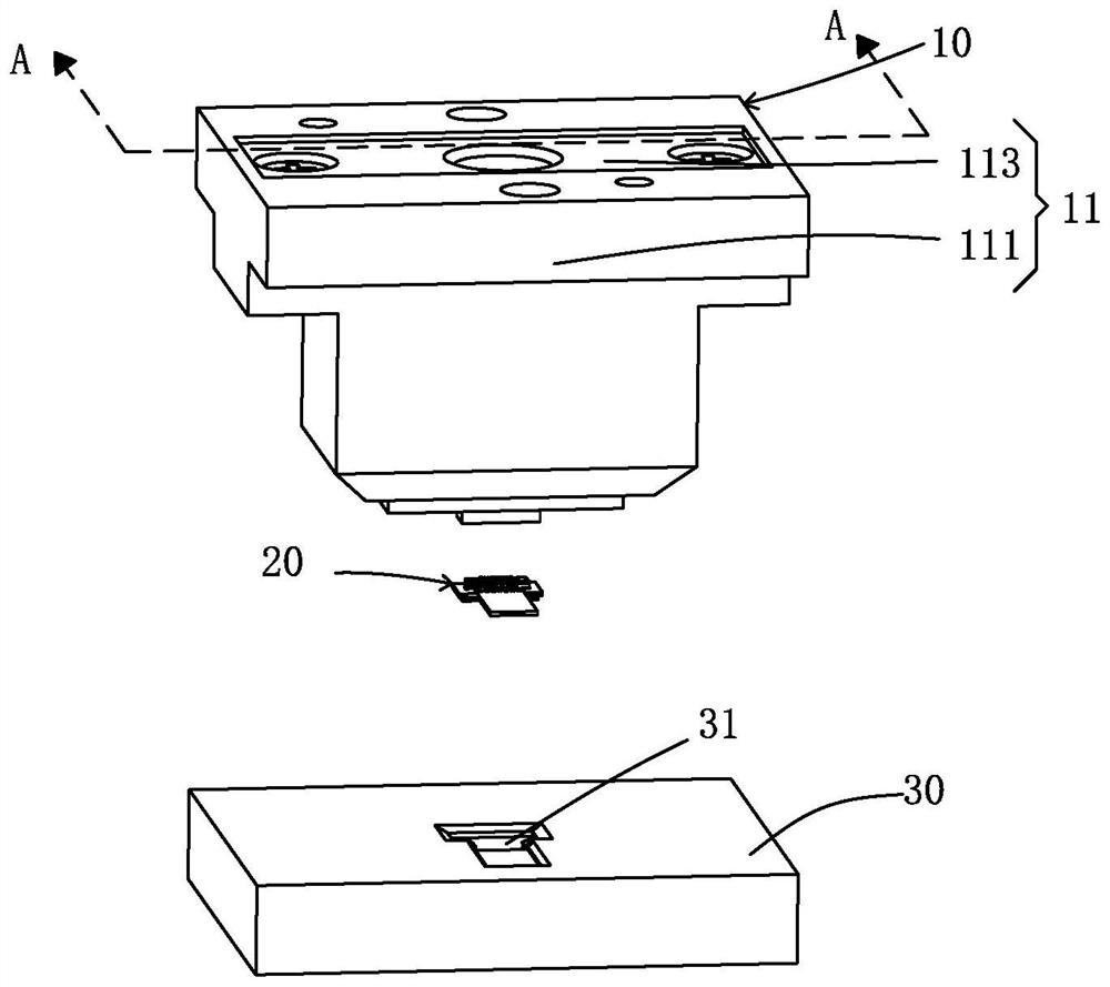
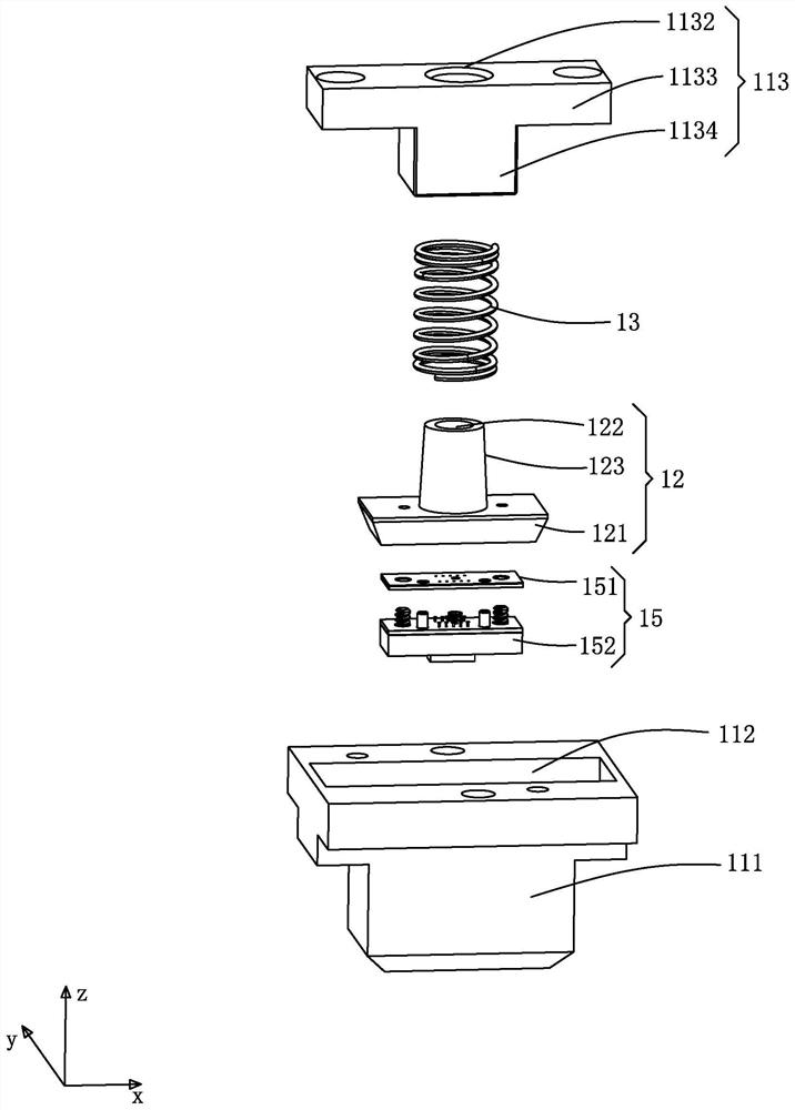
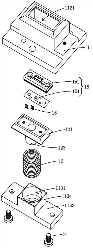
[0030] Please see figure 1 and 2 , an embodiment of the present invention provides a transmission line 20 testing device for testing the transmission line 20, specifically, the transmission line 20 testing device includes a floating probe assembly 10 and a positioning seat 30; the positioning seat 30 is used to support The transmission line 20, the probe assembly 10 is used to electrically connect with the transmission line 20; during testing, the transmission line 20 to be tested is first installed on the positioning seat 30, and then the floating probe assembly 10 and the positioning seat 30 are connected to each other. Relatively move and approach until the floating probe assembly 10 abuts against the transmission line 20 to be tested. When the floating probe assembly 10 and the positioning seat 30 are fitted in place, the two are electrically conne...


PUM


Abstract

The present invention provides a transmission line testing device, which is used for testing transmission lines. The transmission line testing device includes a floating probe assembly and a positioning seat; the positioning seat is used to support the transmission line, and the floating probe assembly is used to communicate with the The transmission line is electrically connected; the floating probe assembly includes a base with a receiving cavity, a positioning block installed in the receiving cavity, an elastic member connected between the base and the positioning block, and a positioning block installed in the positioning block. The probe part on the block, the positioning block and the probe part on the block can move relative to the base under the support of the elastic member. In the transmission line test device provided by the present invention, the cooperation between the floating probe assembly and the positioning seat can support the translation or rotation of the transmission line to be tested in 6 degrees of freedom, so that even in the initial contact between the floating probe assembly and the transmission line to be tested When the position is deviated, the test work can continue, and the probe assembly and the transmission line to be tested can be accurately and stably contacted.

Description

【Technical field】 [0001] The invention relates to the technical field of testing devices, in particular to a transmission line testing device. 【Background technique】 [0002] With the development of 5G and consumer electronics technology, research on multi-antenna technology has a long history. The space available for the layout of traditional RF coaxial transmission lines is getting smaller and smaller, so new transmission line structures (including FPC and connectors) have emerged as the times require. [0003] For the design of multi-antenna RF transmission lines, flexible material circuits (including connectors) are mainly used for RF transmission, and the superiority of its RF transmission performance plays a vital role. [0004] Testing the RF performance of transmission lines has become an important item in the mass production test of transmission lines. A stable, reliable and accurate test fixture can well measure the RF performance of the transmission line, and th...

Claims


Application Information

Patent Timeline
Patent Type & Authority Patents(China)
IPC IPC(8): H01R12/91H01R13/502H01R13/627H01R13/629
CPCH01R12/91H01R13/502H01R13/627H01R13/629
Inventor 何家勇张华詹大伟陈勇利
Owner AAC PRECISE MFG TECH CHANGZHOU
Learn More