Interface for connecting electric motor to wiring harness, and electric motor

A technology of electric motors and cable harnesses, applied in the field of electric motors, can solve problems such as suboptimal contact safety

Inactive Publication Date: 2020-06-12
U SHIN DEUT ZUGANGSSYST
View PDF11 Cites 0 Cited by
  • Summary
  • Abstract
  • Description
  • Claims
  • Application Information

AI Technical Summary

Problems solved by technology

However, this is not optima

Method used


Image

  • Interface for connecting electric motor to wiring harness, and electric motor
  • Interface for connecting electric motor to wiring harness, and electric motor
  • Interface for connecting electric motor to wiring harness, and electric motor

Examples


Embodiment Construction

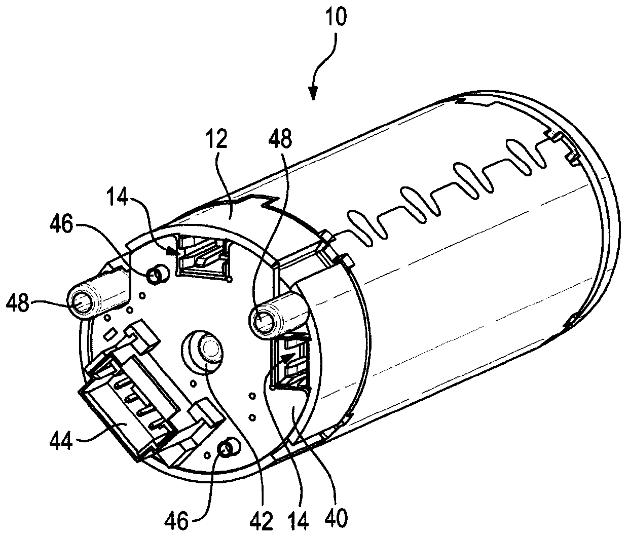
[0020] exist figure 1 An electric motor 10 can be seen in the figure, which is especially designed for use in a servo drive, such as it is used in a motor vehicle. One example is a spindle drive.

[0021] On its side facing away from the output side, the electric motor is provided with connections for connecting the electric motor to a cable harness. The interface is used here to transmit electrical energy for driving the electric motor 10 and to connect the electric motor 10 to a control unit.

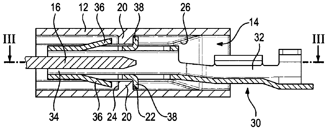
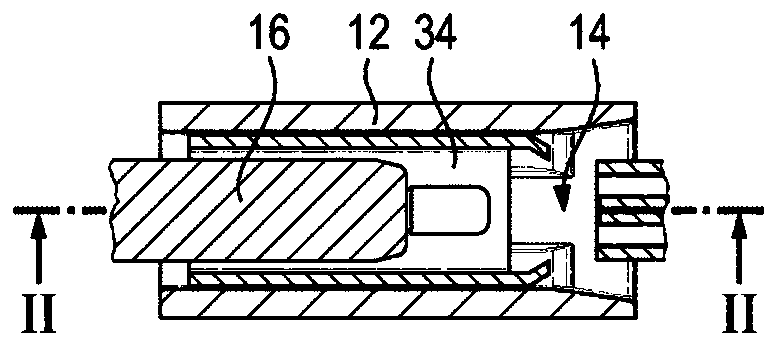
[0022] The interface has a housing 12 which is designed here as a brush holder housing. The plug-in cavity is integrated in the housing 12 (see also figure 2 and 3 ), the plug-in cavity is arranged such that the contact piece 16 of the motor extends into each plug-in cavity 14 . The two contact blades 16 serve to transmit the electric drive power to the electric motor 10 .

[0023] Each plug cavity 14 is provided with a narrowing 20 which has shoulders on opposite sides. The s...


PUM


Abstract

The invention relates to an interface for connecting an electric motor (10) to a wiring harness, comprising a motor-side housing (12), in which two plugging chambers (14) are provided. A contact blade(16) of the electric motor (10) extends into each plugging chamber (14). Each plugging chamber (14) is provided with a stop (22) for a plugging sleeve (30) and with a latching element (24) for the plugging sleeve (30). The invention further relates to an electric motor (10) having such an interface.

Description

technical field [0001] The invention relates to a connection for connecting an electric motor to a cable harness and to an electric motor with such a connection. Background technique [0002] In many applications it is common to solder the cables via which the electrical energy for driving the electric motor is supplied to the corresponding terminals of the electric motor. However, this is advantageous in view of the safety of contact (in any case, the soldering point is designed in accordance with regulations). However, welding entails high expenditure. [0003] It is also known to provide cables with plug contacts which are plugged into electrical terminals of the electric motor. However, this is not optimal with regard to contact safety. Contents of the invention [0004] The object of the present invention is to reliably connect the electric motor to the cable harness without having to use high effort for this. [0005] In order to achieve this object, according to...

Claims


Application Information

Patent Timeline
IPC IPC(8): H02K5/22H01R13/432H02K5/14
CPCH01R13/432H01R2201/10H02K5/14H02K5/225
Inventor 弗兰克·库默平尾英司矢张俊行
Owner U SHIN DEUT ZUGANGSSYST
Why Eureka
Try Eureka