Clamp and machining assembly
A fixture and processing tool technology, applied in metal processing mechanical parts, metal processing equipment, clamping and other directions, can solve the problems of workpiece scrap, affecting processing efficiency, and workpiece carry-out.
- Summary
- Abstract
- Description
- Claims
- Application Information
AI Technical Summary
Problems solved by technology
Method used
Image
Examples
Embodiment 1
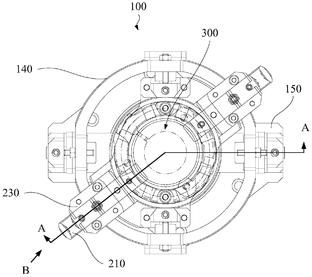
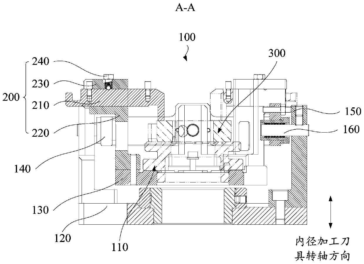
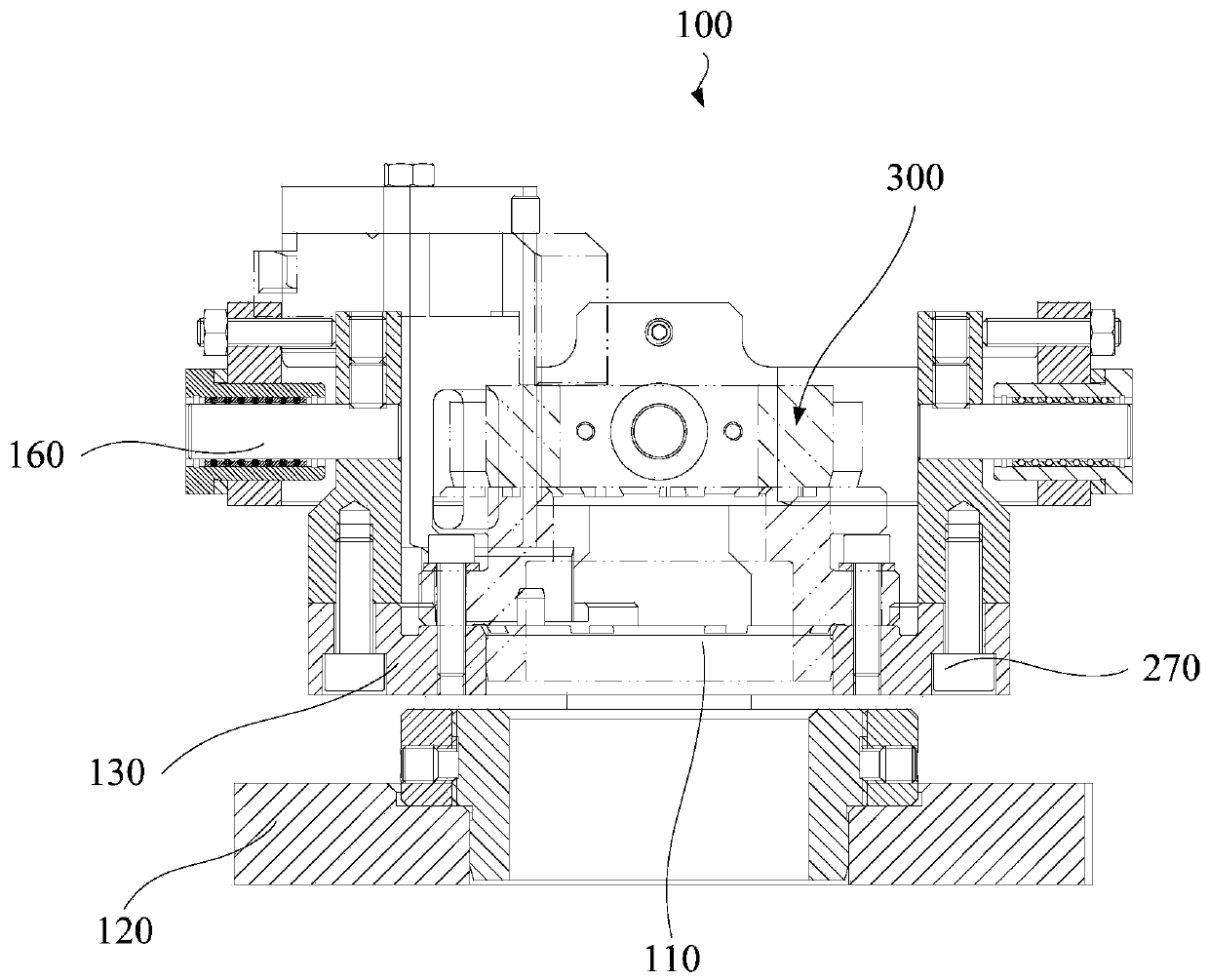
[0052] Such as Figure 1 to Figure 9 As shown, the embodiment of the first aspect of the present invention proposes a fixture 100 used in conjunction with an inner diameter machining tool (not shown) for machining the inner diameter of a workpiece 300 . The fixture 100 includes: a positioning device 110 and a limiting device 200. The limiting device 200 includes a stopper 210. Along the direction of the rotation axis of the inner diameter processing tool, there is a gap between the stopper 210 and the positioning device 110. In the plane of the rotating shaft, the block 210 is configured to move relative to the positioning device 110 .
[0053] In this embodiment, the fixture 100 is used in conjunction with an inner diameter machining tool for machining the inner diameter of the workpiece 300 . Such as figure 1 , figure 2 with image 3 As shown, the fixture 100 includes a positioning device 110 and a limiting device 200. The positioning device 110 is configured to limit t...
Embodiment 2
[0055] Such as Figure 1 to Figure 9 As shown, in one embodiment of the present invention, the clamp 100 includes: a positioning device 110, a limiting device 200, a base 120 and a floating plate 130, the floating plate 130 is arranged between the base 120 and the positioning device 110, the floating plate 130 and the base 120 is connected with the positioning device 110, wherein the limit device 200 also includes a connection assembly, the connection assembly is connected with the floating plate 130, and is located on the side of the floating plate 130 away from the base 120, the connection assembly is provided with a guide groove 222, a stopper 210 is configured to move along guide slot 222 .
[0056] In this example, if figure 1 , figure 2 with image 3 As shown, the clamp 100 includes a base 120 and a floating plate 130, and the limit device 200 also includes a connection assembly. The floating plate 130 is located between the base 120 and the positioning device 110. O...
Embodiment 3
[0058] Such as Figure 1 to Figure 9 As shown, the clamp 100 provided by an embodiment of the present invention, on the basis of the above-mentioned embodiment 2, further, the connecting assembly includes: a first connecting piece 220, one end of the first connecting piece 220 is connected to the floating plate 130, The other end is provided with a guide groove 222 ; the cover plate 230 is provided at the other end of the first connecting piece 220 and connected with the first connecting piece 220 , and the stopper 210 is located between the first connecting piece 220 and the cover plate 230 .
[0059] In this example, if Figure 4 , Figure 5 with Image 6 As shown, the connecting assembly includes a first connecting piece 220 and a cover plate 230, one end of the first connecting piece 220 is connected to the floating plate 130, and the other end is provided with a guide groove 222, the guide groove 222 runs through the first connecting piece 220, and the cover plate 230 ...
PUM
| Property | Measurement | Unit |
|---|---|---|
| Depth | aaaaa | aaaaa |
Abstract
Description
Claims
Application Information
 - R&D
- Intellectual Property
- Life Sciences
- Materials
- Tech Scout
- Unparalleled Data Quality
- Higher Quality Content
- 60% Fewer Hallucinations
Browse by: Latest US Patents, China's latest patents, Technical Efficacy Thesaurus, Application Domain, Technology Topic, Popular Technical Reports.
© 2025 PatSnap. All rights reserved.Legal|Privacy policy|Modern Slavery Act Transparency Statement|Sitemap|About US| Contact US: help@patsnap.com


