
Injection and metering device

A technology of distributing device and injection position, applied in the direction of muffler device, exhaust device, exhaust gas treatment, etc., can solve the problems of expensive and expensive manufacturing, installation and maintenance, undefined opening behavior of the nozzle needle, etc., and achieve the effect of low cost

Inactive Publication Date: 2013-05-08
ROBERT BOSCH GMBH
View PDF5 Cites 4 Cited by
  • Summary
  • Abstract
  • Description
  • Claims
  • Application Information

AI Technical Summary

Problems solved by technology

The combination of electric pumps and electronically controlled metered dispensing valves is complex and expensive to manufacture, install and maintain
The pressure waves generated by the operation of the metering pump and / or the closing of the valve may be passed between the metering pump and the metering valve through the pressure line required in this combination between the metering pump and the metering valve. pass between, superimpose on each other and lead to undefined opening behavior of the nozzle needle

Method used


Image

  • Injection and metering device

Examples


Embodiment Construction

[0026] In the following description, descriptions such as "upper" and "lower" are used to better explain the schematic diagrams of the embodiments of the invention shown in the drawings, and cannot limit the invention to the shown embodiments or to certain Orientation or installation position.

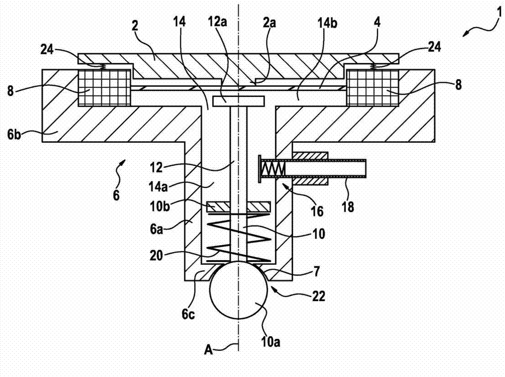
[0027] The spray and metering device 1 has a substantially rotationally symmetrical holding body 6 about a longitudinal axis A, which has a lower holding body region 6a and an upper holding body region 6b. The lower holding body region 6a has a smaller cross section in a plane lying perpendicular to the longitudinal axis A than the upper holding body region 6b.

[0028] A pressure and injection chamber 14 is formed in the holding body 6 eg rotationally symmetrically about the longitudinal axis A, having an upper region 14b and a lower region 14a. The upper region 14b of the pressure and injection chamber 14 formed in the upper holder region 6b has a larger diameter in a plane arranged...


PUM


Abstract

The invention relates to an injection and dosing device (1), in particular for injecting a fluid into an exhaust tract of a combustion engine, comprising a compression and injection space (14), which is designed to receive the fluid to be injected and has at least one injection opening (22); a movable pressure element (4), which is designed such that the pressure in the compression and injection space (14) can be varied by moving the pressure element (4) between an intake position, in which the pressure in the compression and injection space (14) is at a minimum, and an injection position, in which the pressure in the compression and injection space (14) is at a maximum; and a closing element (10), which can be moved between a closing position, in which said element closes the injection opening (22), and an open position, in which said element exposes the injection opening (22). The pressure element (4) and the closing element (10) are coupled via at least two mechanisms of action that are independent of each other, and each of the independent mechanisms of action is capable on its own of having the effect that a movement of the pressure element (4) from the intake position into the pressure position results in a movement of the closing element (10) from the closing position into an open position.

Description

technical field [0001] The invention relates to an injection and metering device, in particular to an injection and metering device for injecting liquid into an exhaust line. Background technique [0002] The requirements placed on the exhaust gas quality of internal combustion engines, in particular internal combustion engines for driving motor vehicles, have been continuously increasing in recent years. Especially in diesel engines NO x Emissions are a problem, which are suppressed by means of so-called SCR catalysts. Environmentally Harmful NO in SCR Catalysts x With the aid of NH, usually in the form of an aqueous urea solution, fed to the catalyst 3 Convert to N 2 and H 2 O. [0003] To deliver the urea solution a dosing system is required, which conventionally consists of an electric dosing pump, which generates the desired injection pressure, and a dosing valve, which dispenses the required injection quantity . The combination of an electric pump and an electr...

Claims


Application Information

Patent Timeline
IPC IPC(8): F01N3/20
CPCF01N2610/1433F01N3/2066F01N2610/1453Y02T10/24F01N2610/02Y02T10/12
Inventor S·勒施
Owner ROBERT BOSCH GMBH
Learn More