
Coiled tubing speed tubular column suspending and sealing device

A speed string and sealing device technology, applied in sealing/packing, wellbore/well components, earth-moving drilling, etc., can solve the problems of coiled tubing falling off, poor sealing reliability, time-consuming and labor-intensive, etc., to improve work efficiency, Avoid leakage problems, fast and convenient operation

Pending Publication Date: 2019-01-25
SHANDONG KERUI WELL CONTROL SYST MFG
View PDF0 Cites 2 Cited by
  • Summary
  • Abstract
  • Description
  • Claims
  • Application Information

AI Technical Summary

Problems solved by technology

[0003] 1. The slips cannot be effectively fixed, and the coiled tubing will slide upward and vibrate due to the influence of the pressure and air flow in the well
Due to the lack of effective fixation of the slip hanger, it is very easy to cause loosening, and even cause the coiled tubing to fall off, resulting in accidents
[0004] 2. There is only one set of sealing components, and the sealing reliability is poor
After the coiled tubing is suspended, it is necessary to cut the coiled tubing, which has only one seal with the natural gas in the well. Once the gas in the well leaks, it will bring great hidden dangers to the safety of the wellhead operators.
[0005] 3. After the coiled tubing is put in place, it is necessary to configure an operation window to lower the slips. The operation is complicated, time-consuming and labor-intensive

Method used


Image

  • Coiled tubing speed tubular column suspending and sealing device
  • Coiled tubing speed tubular column suspending and sealing device
  • Coiled tubing speed tubular column suspending and sealing device

Examples


Embodiment Construction

[0035] The following is a further description of the present invention in conjunction with the accompanying drawings and embodiments.

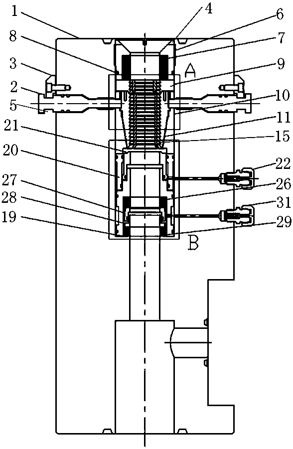
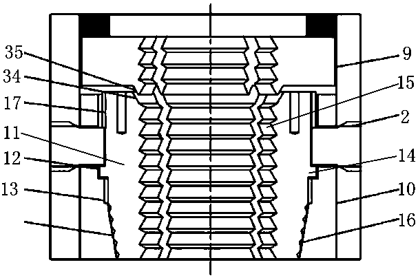
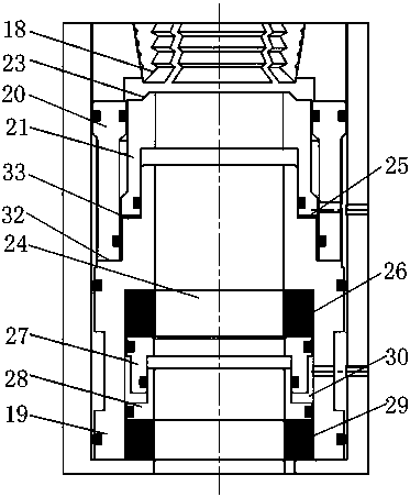
[0036] refer to Figure 1-Figure 6 As shown, a coiled tubing velocity string suspension sealing device includes a body assembly, a top sealing assembly, a slip assembly, an unlocking mechanism and a bottom sealing assembly.

[0037] in:

[0038] The body assembly includes a suspension body 1 , a slip activation pin 2 and a limit protection ring 3 . The slip activation pin 2 is installed on the outer peripheral surface of the suspension body 1, and one end thereof penetrates the suspension body 1 and is in movable contact with the outer surface of the slips. The limit protection ring 3 is arranged on the outer surface of the suspension body 1 to limit the unscrewing position of the slip activation pin, and the middle part of the suspension body 1 is provided with a suspension hole 4 for hanging the pipe string. The outer surface of the slip ...


PUM


Abstract

The invention discloses a coiled tubing speed tubular column suspending and sealing device. The coiled tubing speed tubular column suspending and sealing device comprises a body component, a top sealing component, a slip component, an unlocking mechanism and a bottom sealing component. The top sealing component comprises a guide nut, a top sealing ring and an O-type sealing ring. The body component comprises a suspending body, a slip stimulating pin and a limiting protection ring. The slip component comprises an elastic slip check ring installed in a suspending hole, a slip base and multiple pieces of slips. The unlocking mechanism comprises a sealing bush, a support sleeve, an unlocking piston and an unlocking one-way valve. The bottom sealing component comprises an upper sealing ring, anupper piston, a lower piston and a lower sealing ring which are installed in a bottom sealing cavity from top to bottom. The coiled tubing speed tubular column suspending and sealing device is capable of rapidly and stably suspending a coiled tubing speed tubular column without an operating window, reliably sealing, rapidly and effectively unlocking, and improving working efficiency.

Description

technical field [0001] The invention relates to the technical field of coiled tubing velocity strings in the oil drilling industry, in particular to a coiled tubing velocity string suspension sealing device. Background technique [0002] With the development of coiled tubing technology, the use of coiled tubing as a completion string to effectively avoid or slow down the impact of bottomhole fluid accumulation on later production has been more and more used in low pressure and low production gas wells. However, in actual use, there are mainly the following shortcomings: [0003] 1. The slips cannot be fixed effectively, and the coiled tubing will slide upward and vibrate due to the influence of the pressure and air flow in the well. Due to the lack of effective fixation of the slip hanger, it is very easy to cause loosening, and even cause the coiled tubing to fall off, resulting in accidents. [0004] 2. There is only one set of sealing components, and the sealing reliabi...

Claims


Application Information

Patent Timeline
IPC IPC(8): E21B33/03
CPCE21B33/03
Inventor 郭晓晓于小涛葛居良牛丛丛程慧云
Owner SHANDONG KERUI WELL CONTROL SYST MFG
Learn More