Full-automatic barrier-free passing device capable of being used for bus

A passing device, fully automatic technology, applied in the layout of pedals or ladders, vehicle components, transportation and packaging, etc., can solve the problems of complex structure, difficult installation, low operating efficiency, etc., to achieve broad market prospects and applicable models. , the effect of simple structure

Pending Publication Date: 2020-06-16
HENAN UNIV OF SCI & TECH
View PDF0 Cites 2 Cited by
  • Summary
  • Abstract
  • Description
  • Claims
  • Application Information

AI Technical Summary

Problems solved by technology

[0003] As an indispensable part of urban transportation, public transportation plays an indispensable role in the travel of the public; however, the development of barrier-free public transportation in my country has been very slow for a long time. The travel of vulnerable groups such as adults and the elderly has caused serious impacts
[0004] At present, the international and domestic mainstream bus barrier-free devices can be roughly divided into guide plate type and hydraulic lifting table type according to the principle: the first type of guide plate type is to lay an inclined guide plate between the bus rear door compartment floor and the platform floor , although the labor load is reduced compared with the traditional manual handling, it still requires human assistance, and its structural defects also make it only suitable for low-floor buses, and its operating efficiency is relatively low; the second type of hydraulic lifting platform, which is installed A set of lifting platform powered by hydraulic pressure assists passengers to get on and off the bus. Although the operating efficiency has been significantly improved compared with the first type, the use of hydraulic mechanisms has also led to its high cost, complex structure, difficult installation, and difficult maintenance. And other issues

Method used


Image

  • Full-automatic barrier-free passing device capable of being used for bus
  • Full-automatic barrier-free passing device capable of being used for bus
  • Full-automatic barrier-free passing device capable of being used for bus

Examples


Embodiment Construction

[0030] The present invention will be described in further detail below in conjunction with the accompanying drawings and specific embodiments.

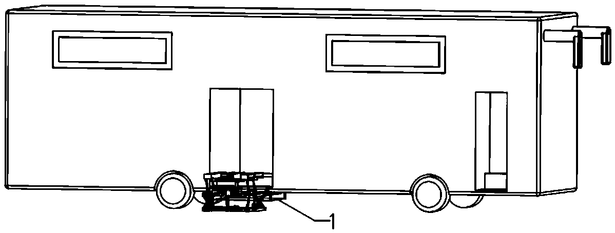
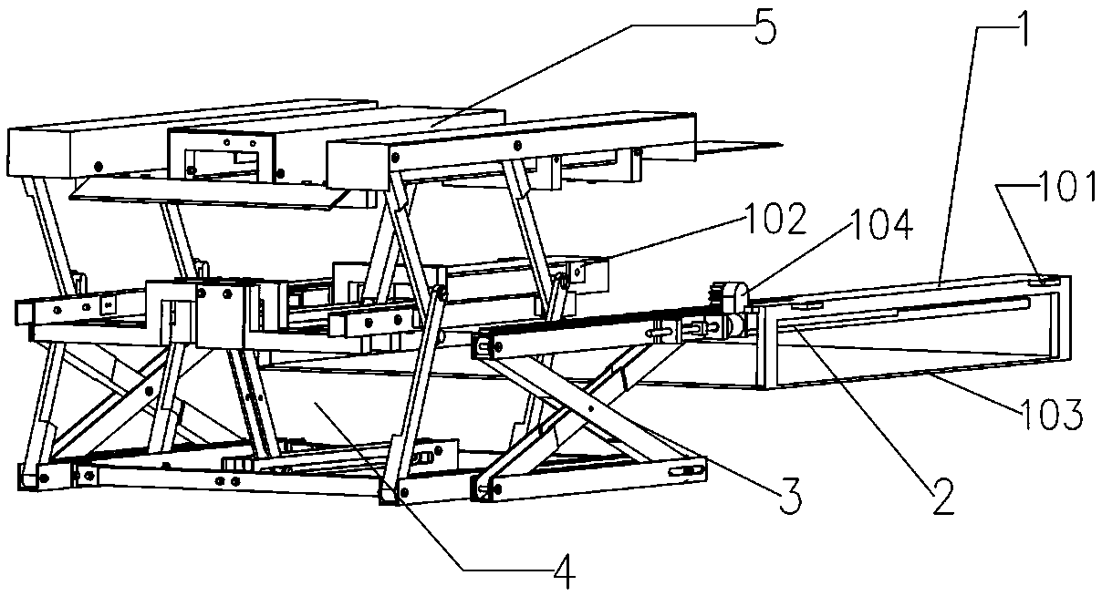
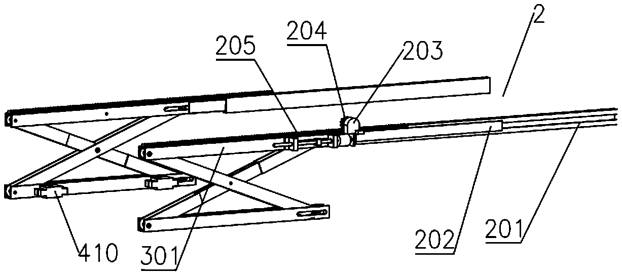
[0031] Such as figure 1 , the present invention proposes a fully automatic barrier-free passing device that can be used for buses, which is integrally fixed under the chassis of the rear door of the bus to assist passengers to get on and off the bus barrier-free, such as figure 2 As shown, the device includes a mounting base 1, a combined slide rail mechanism 2, a retractable mechanism 3, a lifting mechanism 4 and a connecting plate assembly 5, the mounting base 1 is fixedly connected with the bus chassis, and the combined slide rail mechanism 2 are symmetrically arranged on both sides of the installation base 1 in two left and right sets. The retractable mechanism 3 is connected to the combined slide rail mechanism 2 and is arranged in two sets correspondingly. The retractable mechanism 3 can move from the installation base along th...


PUM


Abstract

The invention relates to a full-automatic barrier-free passing device capable of being used for a bus. The device comprises a mounting base, a combined sliding rail mechanism, a retracting and releasing mechanism, a lifting mechanism and a connecting plate assembly, wherein the mounting base is fixedly connected with a bus chassis; the left and right sets of combined sliding rail mechanisms are symmetrically arranged on two sides of the mounting base; the two sets of folding and unfolding mechanisms and the two sets of combined sliding rail mechanisms are connected and correspondingly arranged; the lifting mechanism is arranged on the inner side of the retracting mechanism; a connecting plate assembly is arranged above the lifting mechanism; the mounting base is fixed to a chassis of a rear door of a bus, the direct-current motor serves as a working power source, the ground serves as a main stress point when the device works, passengers are sent into and sent out of the bus through thelifting mechanism and the connecting plate assembly, and therefore the process of assisting the passengers in getting on and getting off the bus is completed, and full-automatic barrier-free passingis achieved.

Description

technical field [0001] The invention relates to the technical field of automobiles, in particular to a fully automatic barrier-free passing device applicable to buses. Background technique [0002] According to data statistics and surveys, there are a large number of elderly and disabled people in my country, in addition to a large number of injured patients, children, pregnant women, etc.; the setting and use of barrier-free facilities are closely related to these groups. [0003] As an indispensable part of urban transportation, public transportation plays an indispensable role in the travel of the public; however, the development of barrier-free public transportation in my country has been very slow for a long time. The travel of vulnerable groups such as people and the elderly has caused serious impacts. [0004] At present, the international and domestic mainstream bus barrier-free devices can be roughly divided into guide plate type and hydraulic lifting table type acc...

Claims


Application Information

Patent Timeline
Patent Type & Authority Applications(China)
IPC IPC(8): B60R3/00B60R3/02
CPCB60R3/007B60R3/02
Inventor 刘恩光肖显张志豪韩晨辉关泽李博涵徐文鑫马心坦梁坤峰
Owner HENAN UNIV OF SCI & TECH
Why Eureka
Try Eureka