Winding drum material unwinding and winding printing tandem axle-free fixing unit

A reel and unit technology, which is applied to the field of reel material unwinding and printing without serial shaft fixed units, can solve the problems of high labor intensity, heavy weight and high physical labor intensity when disassembling the inflatable shaft, so as to improve the subjective effect and improve the The effect of improving the service life and improving the scope of application

Active Publication Date: 2020-06-16
ZHEJIANG MEIGE MACHINERY
View PDF19 Cites 1 Cited by
  • Summary
  • Abstract
  • Description
  • Claims
  • Application Information

AI Technical Summary

Problems solved by technology

[0003] Due to the large size and wide format of coiled materials in industries such as wood-based panels, home furnishing, flooring, packaging, and decoration, the corresponding roll material positioning air shaft has a large width and heavy weight, and the AB shaft does not stop for refueling during the production process. Large, manual shaft loading and unloading is very labor-intensive, and it is easy to damage the parts; in addition, the existing roll material drive is unilateral drive, that is, the drive motor drives one end of the air shaft to rotate; the string shaft type The overall setting of the air expansion key on the air shaft has a better fixing effect during the rotation process with a large torque. The disadvantage is that it needs to be assembled manually, and the labor intensity caused by frequent disassembly of the air shaft is very high.

Method used


Image

  • Winding drum material unwinding and winding printing tandem axle-free fixing unit
  • Winding drum material unwinding and winding printing tandem axle-free fixing unit
  • Winding drum material unwinding and winding printing tandem axle-free fixing unit

Examples


Embodiment Construction

[0031] Further description will be given below in conjunction with the embodiments shown in the accompanying drawings.

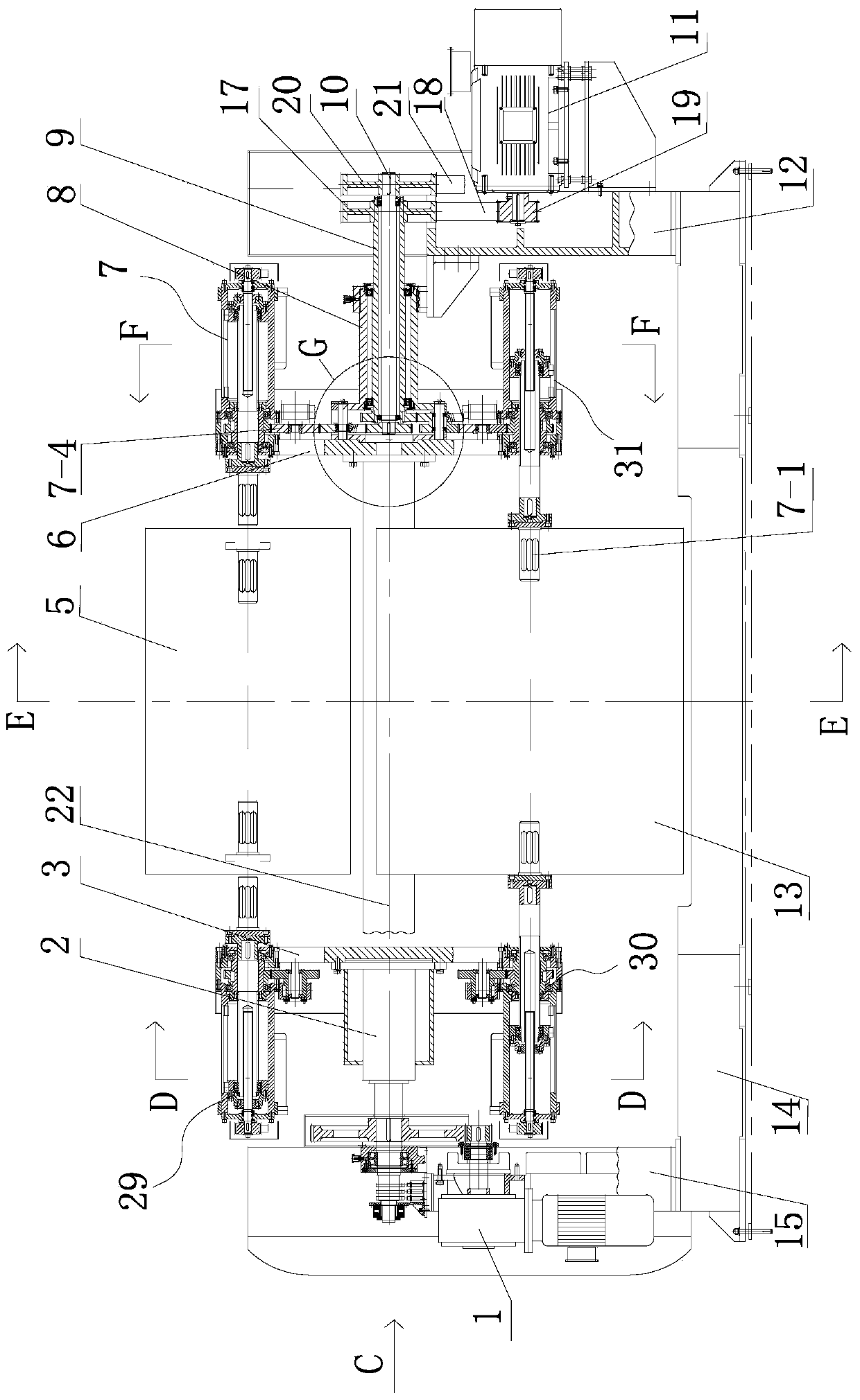
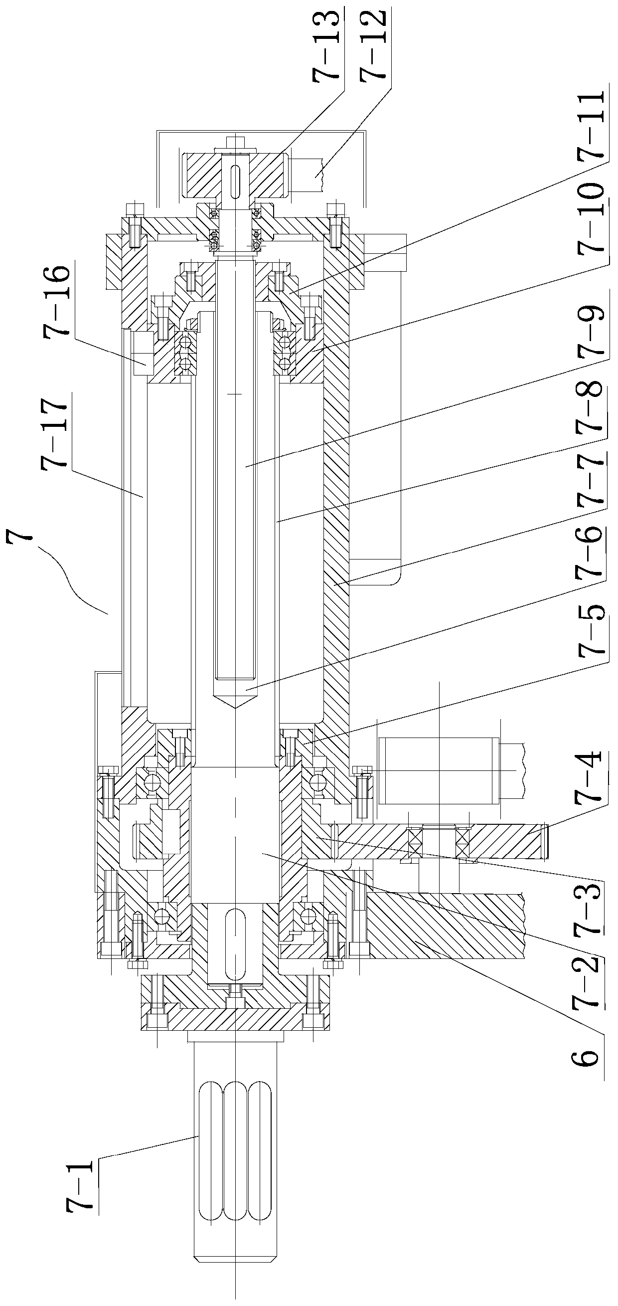
[0032] Such as figure 1 The roll material unwinding and printing without serial axis fixed unit includes a base 14, a left wall panel 15, a right wall panel 12, a transfer tray, a transposition power motor 1, a first left clamping machine head 29, a first right Clamping machine head 7, the second left clamping machine head 30, the second right clamping machine head 31, the first bridge transmission mechanism and the second bridge transmission mechanism. The base is horizontally arranged on the ground; the left wall board and the right wall board are respectively vertically fixed on the left and right sides of the base.

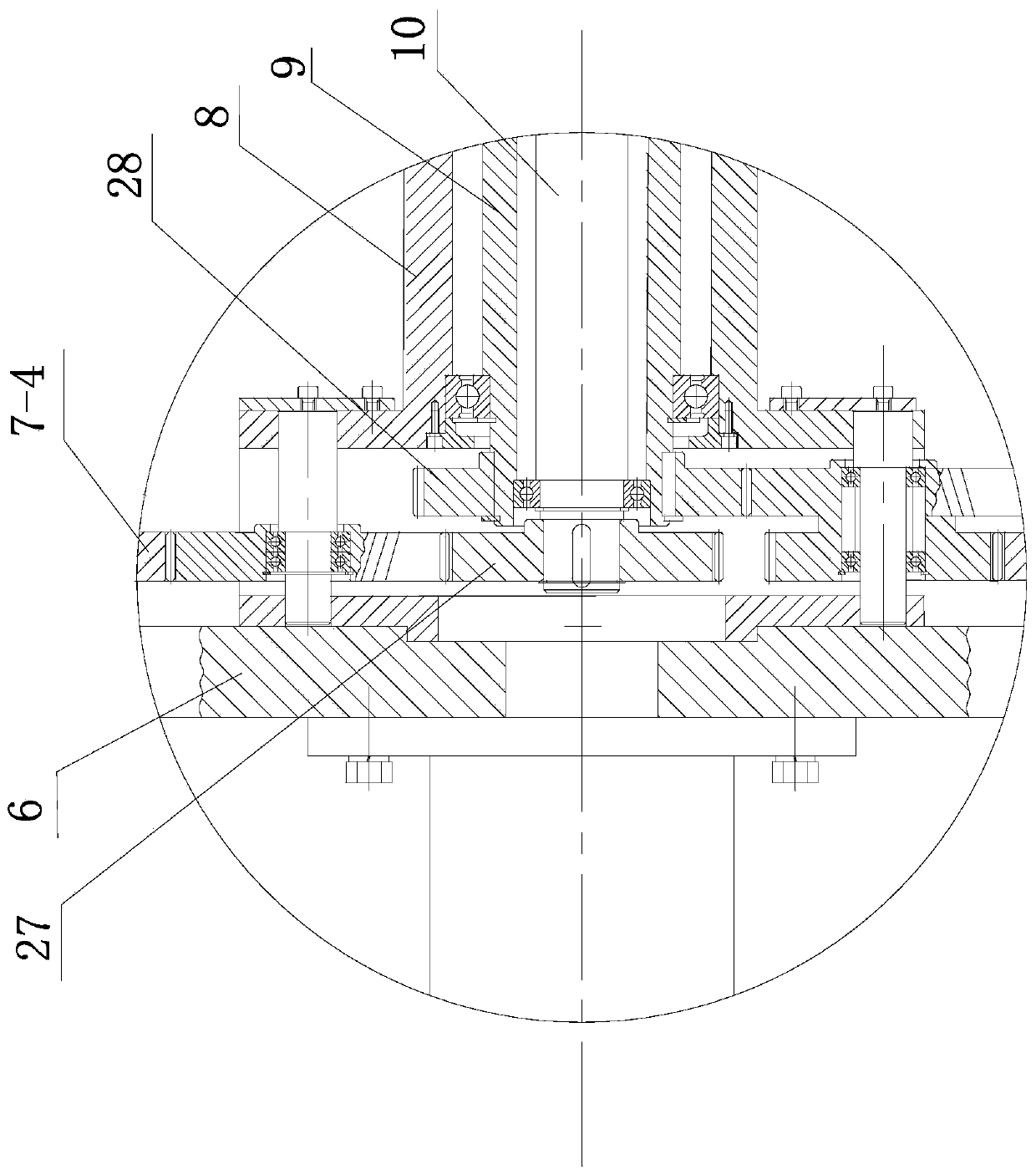
[0033]The transfer tray includes a support head 2 , a left fixed tray 3 , a power input support base 8 and a right fixed tray 6 . The support head is rotatably positioned on the left wallboard around the horizontal axis; the transposition ...


PUM


Abstract

The invention relates to the field of reel material printing and coating production. According to the technical scheme, the winding drum material unwinding and winding printing tandem axle-free fixingunit comprises a base, a left wall plate, a right wall plate, a material rotating disc, a transposition power motor, a first left clamping machine head, a first right clamping machine head, a secondleft clamping machine head, a second right clamping machine head, a first gap bridge transmission mechanism and a second gap bridge transmission mechanism, wherein the left wall plate and the right wall plate are vertically fixed to the left side and the right side of the base, the two ends of the material rotating disc are rotationally positioned on the left wall plate and the right wall plate correspondingly, the transposition power motor drives the material rotating disc to rotate, the first left clamping machine head and the first right clamping machine head are coaxially installed on thematerial rotating disc at an interval so as to clamp an A-axis winding drum material, and the second left clamping machine head and the second right clamping machine head are coaxially installed on the material rotating disc at an interval so as to clamp a B-axis winding drum material. The unit can adapt to winding drum materials with different widths, manual shaft stringing is not needed, the labor intensity of workers is greatly relieved, the winding drum materials are driven to rotate through bilateral transmission, and the unit has the advantages of being reasonable in structure, reliablein work, convenient to operate, suitable for automatic application and high in production efficiency.

Description

technical field [0001] The invention relates to the field of roll material printing and coating production, in particular to a roll material unwinding and printing non-series axis fixing unit. Background technique [0002] In the current roll material printing machine, the unwinding and rewinding of the material is done manually by first passing the air expansion shaft through the shaft hole of the entire roll material, and then using a rickshaw to lift and lower the two ends of the air expansion shaft on the discharge frame. Then blow air to the air shaft to fix the air shaft and the roll material, so as to realize discharging and receiving. In addition, in order to ensure continuous printing in the production process, it is necessary to replace the old roll material that is about to run out with new roll material; therefore, two unwinding shafts for alternate unwinding are generally installed on the unwinding frame of the printing machine, referred to as A axis and B axis...

Claims


Application Information

Patent Timeline
Patent Type & Authority Applications(China)
IPC IPC(8): B65H19/12B65H16/06B65H16/10
CPCB65H16/06B65H16/103B65H19/126B65H2801/21
Inventor 刘国方屈瑶
Owner ZHEJIANG MEIGE MACHINERY
Why Eureka
Try Eureka