LED light bar and method of making the same
A technology of LED light bar and manufacturing method, which is applied in the direction of lighting and heating equipment, electric light source, light source, etc., can solve the problems of easy falling off, easy position deviation of shear marks, high cost, etc., achieve accurate and reliable position, and avoid abnormality The effect of work
- Summary
- Abstract
- Description
- Claims
- Application Information
AI Technical Summary
Problems solved by technology
Method used
Image

Examples
Embodiment 1
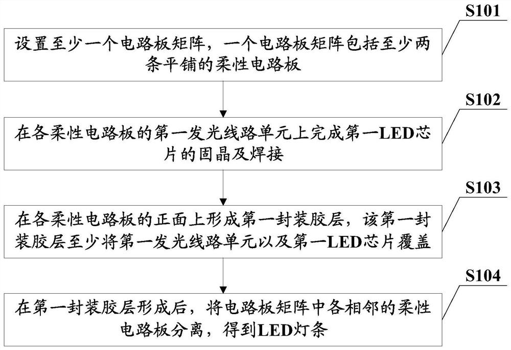
[0062] Aiming at the problems that the existing LED light bar has a relatively thick thickness, high cost, and the shear marks are prone to positional deviation and fall off, this embodiment provides a method that can greatly reduce the thickness and cost of the LED light bar, as well as a cutting A more accurate and reliable LED light bar manufacturing method is provided. The flexible circuit board of the obtained LED light bar is directly provided with a marking hole or a marking notch to mark the cutting position, and the cutting mark is printed on the surface of the light strip packaging adhesive layer, There will be no falling off, and the reliability is better; and because the marking holes are directly set between the adjacent circuit cutting units on the flexible circuit board, the setting position is more accurate and reliable, so as to avoid the cut LED light bar from not working normally; At the same time, the LED light bar can directly set the first LED chip on the ...
example 1
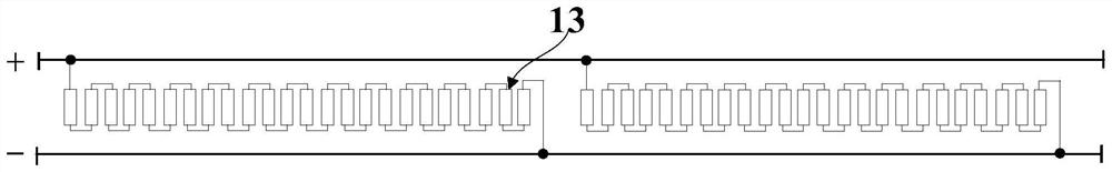
[0083] Example 1: The marking unit includes a first marking unit on the first side, wherein the first marking unit may be a marking hole or a marking notch.
[0084] For example, see Figure 3A and Figure 3B As shown in the flexible circuit board 1, the flexible circuit board includes at least two adjacent circuit cutting units 11, and the circuit cutting units 11 may include at least one first circuit light-emitting unit (such as 2A to 2C shown, but not limited to 2A to 2C ), each first line light-emitting unit includes at least two pairs of electrode connection points 14 respectively used for electrical connection with the positive electrode and the negative electrode of the LED chip, and the electrical connection relationship between each pair of electrode connection points 14 is shown in the above example. , and will not be repeated here. Between adjacent circuit cutting units 11, a marking notch 12 is provided on the first side in the width direction of the flexible...
example 2
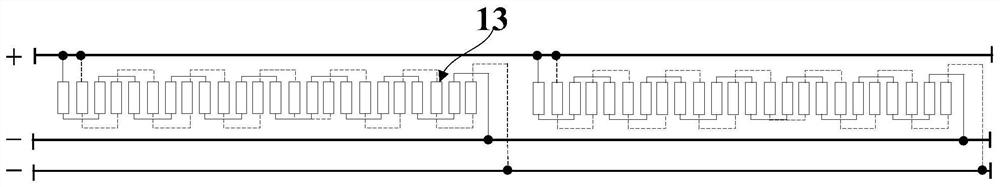
[0086] Example 2: The marking unit includes a fourth marking unit and a fifth marking unit which are located on the first side and the second side respectively and are opposite to each other. The first marking unit in this example may be a marking hole or a marking notch.
[0087] For example, see Figure 5A and Figure 5B As shown in the flexible circuit board 1, the flexible circuit board includes at least two adjacent circuit cutting units 11, and opposite marking notches 12 are respectively provided on the first side and the second side in the width direction of the flexible circuit board. , Figure 5A and Figure 5B The marked notch shown is an arc-shaped notch, and the marks 12 at both ends are the notch after cutting in half, and other figures are similar, and will not be repeated here. Of course, it should be understood that the gap in this example can also be a gap of any other shape, such as a triangle, a polygon, etc., and the size of the gap can be flexibly set...
PUM
 Abstract
Description
Claims
Application Information
 - R&D
- Intellectual Property
- Life Sciences
- Materials
- Tech Scout
- Unparalleled Data Quality
- Higher Quality Content
- 60% Fewer Hallucinations
Browse by: Latest US Patents, China's latest patents, Technical Efficacy Thesaurus, Application Domain, Technology Topic, Popular Technical Reports.
© 2025 PatSnap. All rights reserved.Legal|Privacy policy|Modern Slavery Act Transparency Statement|Sitemap|About US| Contact US: help@patsnap.com