Impact tunnel quick freezer

A quick-freezing machine and impact-type technology, which is applied in the field of impact-type freezing equipment and impact-type tunnel quick-freezing machines, can solve problems such as unreasonable layout and unfavorable airflow rapid circulation.

Active Publication Date: 2021-07-06
SHANGYU GUANFENG FOOD MACHINERY
View PDF5 Cites 0 Cited by
  • Summary
  • Abstract
  • Description
  • Claims
  • Application Information

AI Technical Summary

Problems solved by technology

However, the layout of the existing impact tunnel with quick-freezer is unreasonable, which is not conducive to the rapid circulation of airflow

Method used


Image

  • Impact tunnel quick freezer
  • Impact tunnel quick freezer
  • Impact tunnel quick freezer

Examples


Embodiment 1

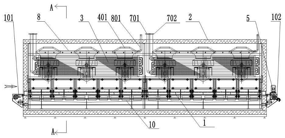
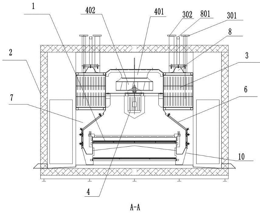
[0024] Such as figure 1 , 2 As shown, an impact tunnel quick-freezing machine includes a conveyor belt 1 for conveying articles, a quick-freezing tunnel 2 through which the conveyor belt passes, and a refrigeration device arranged in the quick-freezing channel, and the refrigeration device includes an evaporator 3 for cooling airflow, The blower fan 4 and the motor 5 that realize the air circulation drive the conveyor belt to circulate, and the articles are placed on the feed end 101 of the conveyor belt, and are sent out from the discharge port 102 after being refrigerated by the air flow. On the article, the upper part of the wind deflector is provided with the fan that communicates with the inner and outer spaces of the wind deflector, and the air inlet 401 of the fan communicates with the lower part of the conveyor belt through the outer air duct 7 outside the wind deflector, that is, the air guide Between the outside of the hood and the tunnel is an outer air duct, on wh...

Embodiment 2

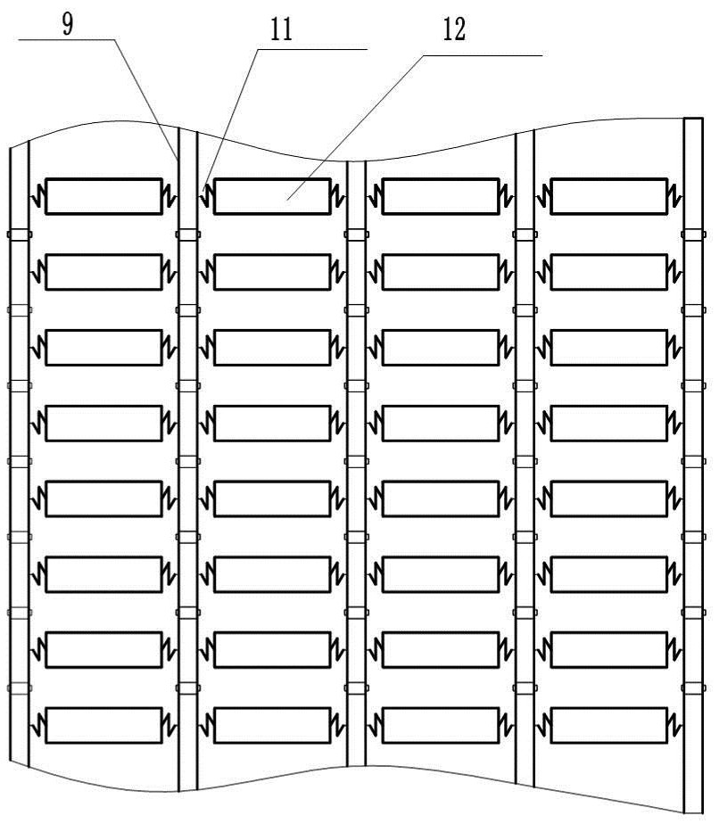
[0026] Such as image 3 , 4 As shown, the conveyor belt includes several parallel chains 9 along the conveying direction, and a turning roller 12 is arranged between the chains, and the two ends of the turning roller are connected with two adjacent chains through temperature deformation elements 11, so that As the temperature changes, the temperature deformation element makes the rotating roller rotate, thereby realizing the rotation of the items on the conveyor belt as the temperature changes, so that the items can be cooled quickly and evenly. There is a cavity inside the rotating roller, and a phase-change energy storage medium 13, such as paraffin, is stored in the cavity, so as to realize continuous cooling of the bottom of the article and supplement the deficiency of the air blown from above; when the article leaves the conveyor belt, the conveyor belt When turning to the bottom, the roller can also absorb the remaining cold energy passing through the airflow of the con...

Embodiment 3

[0029] Such as Figure 5 , 6 As shown, the temperature deformation element can also be a coil spring 112 (and a plane helical spring) formed by a thermal bimetallic sheet. The spring rotates to drive the roller to rotate. The bimetal sheet is also called a thermal bimetal sheet. Since the thermal expansion coefficients of each component layer are different, when the temperature changes, the deformation of the active layer is greater than that of the passive layer, so that the whole bimetal sheet will bend to the side of the passive layer. , then the curvature of the composite material changes to produce deformation.


PUM


Abstract

The invention provides an impact tunnel quick-freezing machine, which relates to impact freezing equipment. It solves the problem of unreasonable arrangement in the prior art, which is not conducive to the rapid circulation of airflow. The impact tunnel quick-freezing machine includes a conveyor belt for conveying items, a quick-freezing tunnel through which the conveyor belt passes, and a refrigeration device arranged in the quick-freezing channel. The upper cover is provided with a deflector to guide the air flow to the items on the conveyor belt. The upper part of the deflector is provided with the fan that communicates with the inner and outer spaces of the deflector. The air inlet of the fan and the lower part of the conveyor belt pass through The outer air duct outside the cover is connected. The present invention facilitates the airflow circulation through the reasonable arrangement of the evaporator, the fan, and the shroud, and has a simple structure, which can greatly improve the cooling efficiency. Through the conveyor belt that changes with the temperature, the items on the conveyor belt can be moved during the transmission process. .

Description

technical field [0001] The invention belongs to the technical field of freezing equipment, and relates to an impact freezing equipment, in particular to an impact tunnel quick freezing machine. Background technique [0002] The impact tunnel belt quick-freezer is to place the products that need to be frozen on the conveyor belt, and the nozzle above the steel belt directly shoots high-speed cold air onto the products that need to be frozen, quickly reducing the temperature of the steel belt at the contact point with the frozen products, thereby taking away the frozen products. heat under the product. It is mainly used for quick freezing of granular, flake and lump foods such as fruit slices, fruit granules, shrimp, fish fillets, and meat. However, the layout of the existing impact tunnel with quick-freezer is unreasonable, which is not conducive to the rapid circulation of airflow. Contents of the invention [0003] The object of the present invention is to solve the abo...

Claims


Application Information

Patent Timeline
Patent Type & Authority Patents(China)
IPC IPC(8): F25D13/06F25D17/06F25D23/00
CPCF25D13/062F25D17/067F25D23/006F25D2400/30
Inventor 徐国峰田鑫郑尧忠周斌斌阮炯君马银海
Owner SHANGYU GUANFENG FOOD MACHINERY
Why Eureka
Try Eureka