
Physical experiment centripetal force demonstration device

A demonstration device and a technology for physical experiments, applied in the field of centripetal force demonstration devices in physical experiments, can solve the problems of inconvenience in taking out steel balls, errors in measurement results, lack of scientificity, accuracy and comparability, etc., and achieve convenient data recording and experimental variables. Easy, simple structure effect

Inactive Publication Date: 2020-06-16
CHANGSHA UNIVERSITY
View PDF7 Cites 0 Cited by
  • Summary
  • Abstract
  • Description
  • Claims
  • Application Information

AI Technical Summary

Problems solved by technology

[0002] "Centripetal force" is a very important knowledge point in high school physics knowledge. In teaching practice, the theoretical derivation process of this formula is too abstract and difficult for students to understand, and the experimental research carried out basically uses conical pendulum or similar devices. A rough verification of centripetal force lacks scientificity, accuracy and comparability, and the actual effect is not ideal; and the "centripetal force experiment demonstrator" used in textbooks over the years is only semi-quantitative, and the authorized announcement number is CN 106601092 B invention patent Disclosed: a centripetal force demonstration instrument, in which the number of steel balls 8 participating in the centripetal force experiment can only increase in one direction during the experiment, and it is very inconvenient to take out the steel balls 8, so it is difficult to arbitrarily change the mass value in the centripetal force experiment according to the experimental requirements , it is difficult to obtain effective experimental results, and the experimental power is artificially provided, and the measurement results have large errors

Method used


Image

  • Physical experiment centripetal force demonstration device
  • Physical experiment centripetal force demonstration device
  • Physical experiment centripetal force demonstration device

Examples


Embodiment Construction

[0014] In order to make the purpose, technical solutions and advantages of the embodiments of the present invention clearer, the technical solutions in the embodiments of the present invention will be clearly and completely described below in conjunction with the drawings in the embodiments of the present invention. Obviously, the described embodiments It is a part of embodiments of the present invention, but not all embodiments. Based on the embodiments of the present invention, all other embodiments obtained by persons of ordinary skill in the art without creative efforts fall within the protection scope of the present invention.

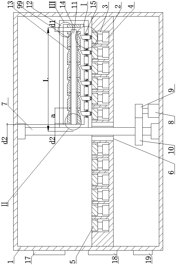
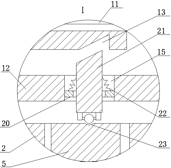
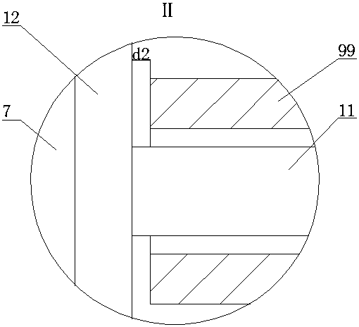
[0015] A physical experiment centripetal force demonstration device, as shown in the figure, includes a first shell 1, the first shell 1 is cylindrical, the inner cylindrical surface of the first shell 1 is fixedly connected to the circular plate 2 in the horizontal direction, and the circular plate 2 is opened There are n ring grooves 3 concentri...


PUM


Abstract

The invention discloses a physical experiment centripetal force demonstration device. The device comprises a first shell, the first shell is cylindrical, the inner cylindrical surface of the first shell is horizontally and fixedly connected with a circular plate; n circular ring grooves which are concentric with the circular plate are formed in the circular plate; the annular grooves are arrangedat equal intervals, a plurality of electric telescopic rods with upward movable rods are fixedly connected to the inner bottom surfaces of the circular ring grooves; horizontal first circular ring plates are arranged in the circular ring grooves; the upper ends of the movable rods of all the electric telescopic rods in the same annular groove are fixedly connected with the lower surface of the corresponding first annular plate, a through hole is formed in the center of the circular plate, a vertical first rotating shaft is arranged in the first shell, the first rotating shaft penetrates through the through hole, and the first rotating shaft is connected with the circular plate and the first shell through rolling bearings. The device is simple in structure and convenient to operate, and experimental variables are easy to control.

Description

technical field [0001] The invention belongs to the field of teaching aids for physics experiments, in particular to a centripetal force demonstration device for physics experiments. Background technique [0002] "Centripetal force" is a very important knowledge point in high school physics knowledge. In teaching practice, the theoretical derivation process of this formula is too abstract and difficult for students to understand, and the experimental research carried out basically uses conical pendulum or similar devices. A rough verification of centripetal force lacks scientificity, accuracy and comparability, and the actual effect is not ideal; and the "centripetal force experiment demonstrator" used in textbooks over the years is only semi-quantitative, and the authorized announcement number is CN 106601092 B invention patent Disclosed: a centripetal force demonstration instrument, in which the number of steel balls 8 participating in the centripetal force experiment can ...

Claims


Application Information

Patent Timeline
Patent Type & Authority Applications(China)
IPC IPC(8): G09B23/10
CPCG09B23/10
Inventor 李正大解琳佘彦武
Owner CHANGSHA UNIVERSITY
Learn More