Anti-disassembly and power-off protection device and use method

A power-off protection device and anti-disassembly technology, which is applied to the coupling device, the parts of the connecting device, and the connection/disconnection of the connecting device, can solve the problems of easy disassembly by mistake, poor safety of the anti-disassembly structure, etc., so as to avoid accidental disassembly. , prolong the service life, avoid the effect of excessive extrusion

Pending Publication Date: 2020-06-16
NANJING KANGNI TECH IND
View PDF0 Cites 0 Cited by
  • Summary
  • Abstract
  • Description
  • Claims
  • Application Information

AI Technical Summary

Problems solved by technology

[0003] In order to solve the deficiencies in the prior art, the present invention provides an anti-dismantlement and power-off protection device and its use method, which solves the technical problems in the prior art that the anti-dismantlement structure of the junction box is poor in safety and easy to be dismantled by mistake

Method used


Image

  • Anti-disassembly and power-off protection device and use method
  • Anti-disassembly and power-off protection device and use method
  • Anti-disassembly and power-off protection device and use method

Examples


Embodiment Construction

[0028] The present invention will be further described below in conjunction with the accompanying drawings. The following examples are only used to illustrate the technical solution of the present invention more clearly, but not to limit the protection scope of the present invention.

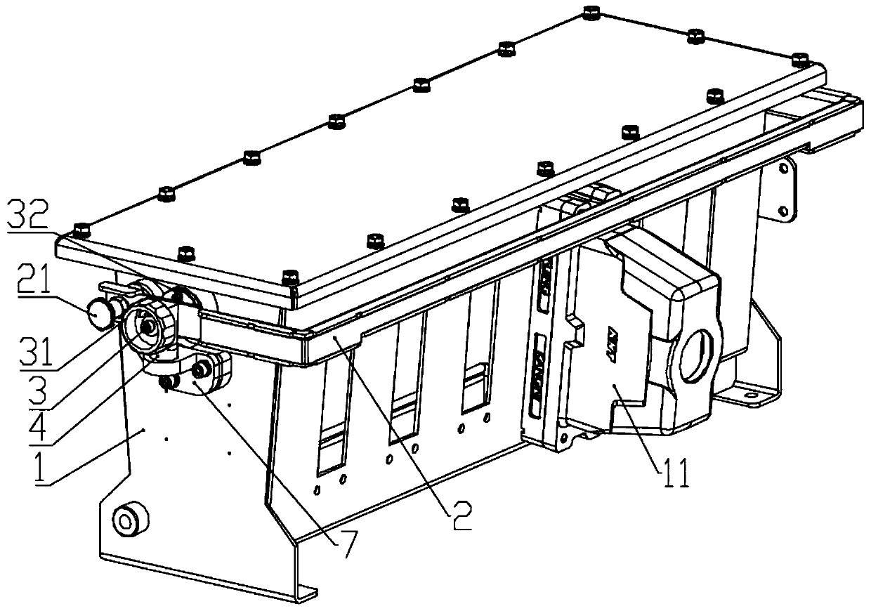
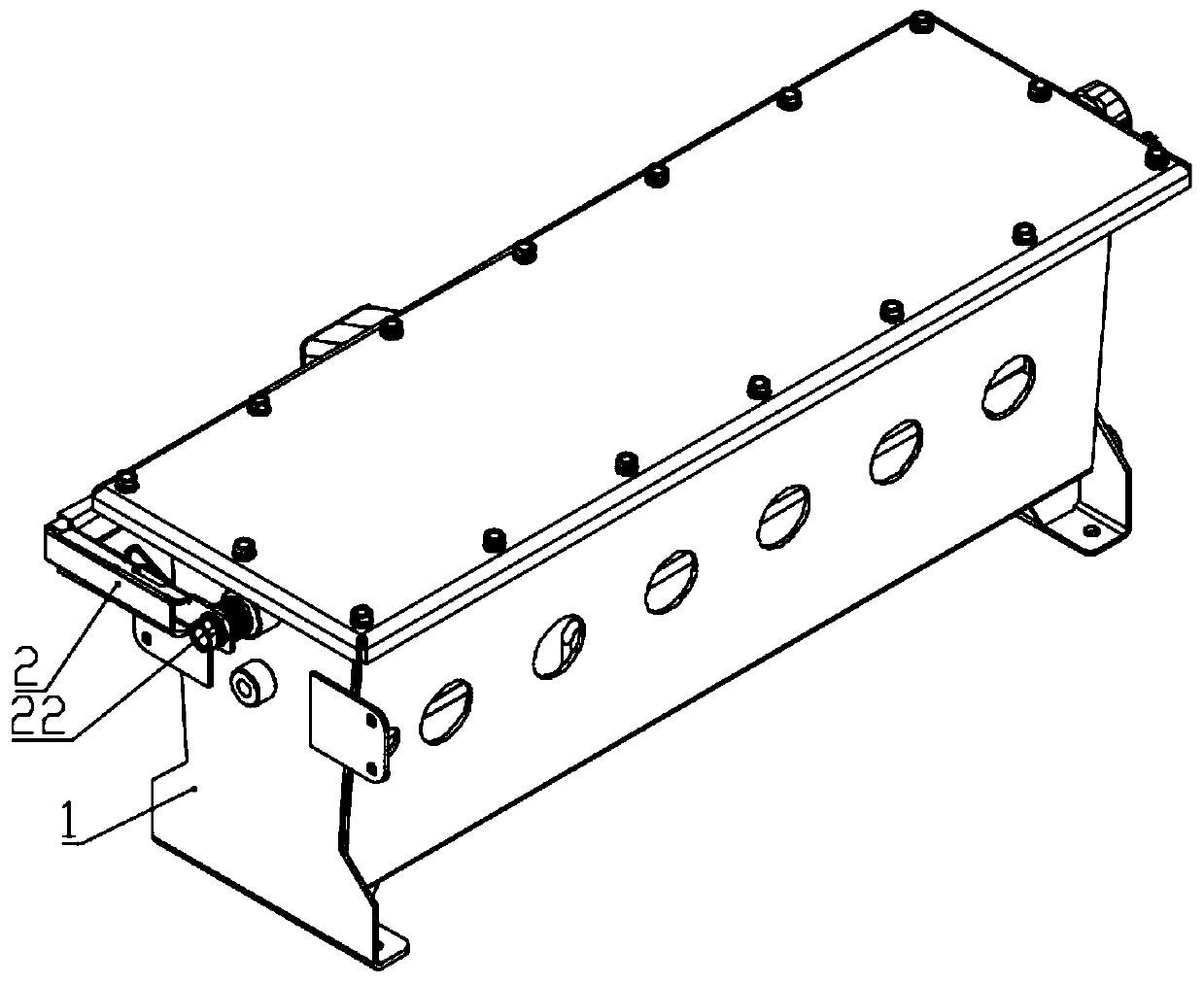
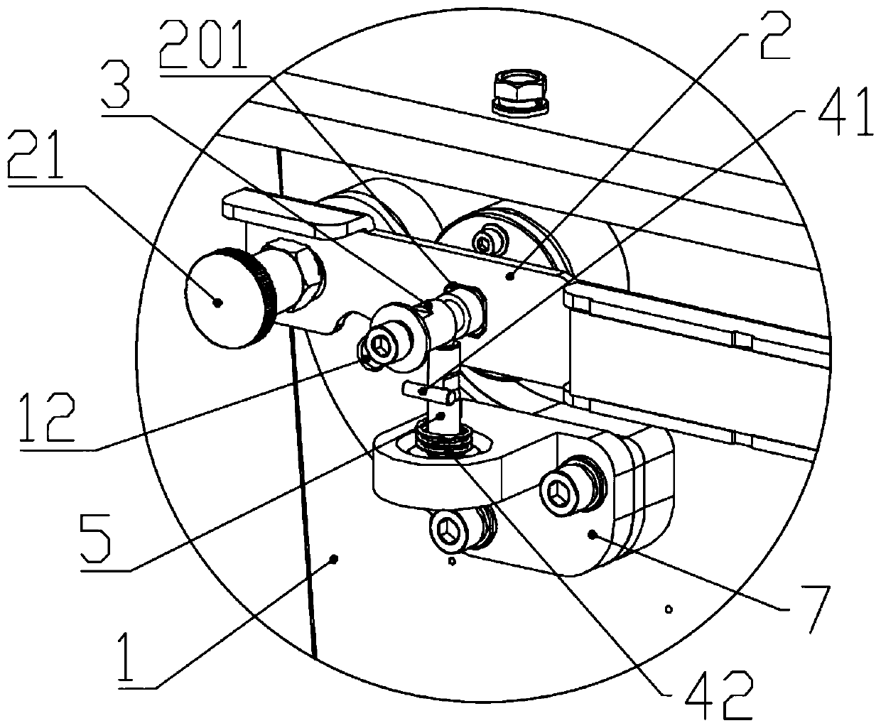
[0029] Such as Figure 1 to Figure 6 As shown: this embodiment discloses a tamper-evident and power-off protection device, including a connector 11 and a wiring unit 1 detachably connected to the connector, and also includes an anti-dismantle shutter mechanism, a shaft lock stop mechanism and a switch linkage The control mechanism, the tamper-proof shutter mechanism includes a shutter 2 and an indexing pin 21, the shutter 2 is used to shield the connection part between the wiring unit 1 and the connector 11, and the shaft lock stop mechanism includes a shaft lock 5 that can slide relative to the rotating shaft 3 , the switch linkage control mechanism includes a rotating shaft 3, the two ends of...


PUM


Abstract

The invention discloses an anti-disassembly and power-off protection device and a use method. The anti-disassembly and power-off protection device comprises a connector and a wiring unit detachably connected to the connector. The device further comprises an anti-disassembly shielding plate mechanism, a shaft lock stop mechanism and a switch linkage control mechanism. The anti-disassembly shieldingplate mechanism comprises a shielding plate and an indexing pin, wherein the shielding plate is used for shielding the connection part of the wiring unit and the connector; the shaft lock stop mechanism comprises a shaft lock capable of sliding relative to the rotating shaft and a shaft lock positioning base capable of sliding relative to the shaft lock; the switch linkage control mechanism comprises a rotating shaft; the two ends of the rotating shaft are connected with a cam and an operating handle respectively, wherein the cam is used for driving the travel switch to be opened or closed, and the rotating shaft is provided with a first clamping section, a second clamping section and an annular groove matched with the shaft lock; the shielding plate is provided with a connecting hole matched with the first clamping section; one end of the shielding plate is connected to the rotating shaft through the connecting hole, and the other end is hinged to the wiring unit; and the travel switch and the shaft lock positioning base are connected to the wiring unit. According to the invention, through controlling of the shielding plate, the protection of the connection part of the wiring unit and the connector is realized.

Description

technical field [0001] The invention relates to the technical field of electrical connector protection, in particular to an anti-disassembly and power-off protection device and a use method. Background technique [0002] Anti-dismantlement and power-off protection devices for electrical connections have always been a non-negligible part of electrical equipment. For example, with the rapid development of the rail transit industry, the protection of the junction box installed on the carriage is becoming more and more important. Once the junction box is dismantled by mistake or maliciously, the entire carriage will not be able to operate normally. Therefore, the tamper protection of the junction box is crucial. On the other hand, the junction box in the prior art has no anti-dismantlement mechanism, which is easy to be dismantled by mistake and live work, and has poor safety. In view of the above reasons, an anti-dismantlement and power-off protection device is needed in the p...

Claims


Application Information

Patent Timeline
Patent Type & Authority Applications(China)
IPC IPC(8): H01R13/639H01R13/70H01R43/26
CPCH01R13/639H01R13/70H01R43/26
Inventor 李福明朱猛施淼森张苗苗
Owner NANJING KANGNI TECH IND
Why Eureka
Try Eureka