
A photoelectric conversion connector

A photoelectric conversion and connector technology, which is applied in the direction of connection, photovoltaic power generation, and parts of connection devices, can solve problems such as easy mopping of the floor, easy entanglement of connecting wires, easy damage and breakage, etc., to achieve enhanced bending strength, shrinkage Easy to bundle and not easy to break

Active Publication Date: 2021-08-27
LULIANG UNIV
View PDF11 Cites 0 Cited by
  • Summary
  • Abstract
  • Description
  • Claims
  • Application Information

AI Technical Summary

Problems solved by technology

[0003] The existing photoelectric conversion connectors have the following problems in the use process: the connecting terminal of the connector is mostly exposed to the air when it is not in use, and the outside of the terminal lacks a good protective structure, and the terminal is easily damaged, which affects the connection. The use of the connector; the connecting wire of the connector has a certain length. During the connection process, the connecting wire that is too long is easy to be entangled and dragged on the floor, which will cause damage to the connecting wire and affect the use of the connector; the connecting wire is connected to the connecting terminal. After being bent many times during use, it is easy to be damaged and broken, which will affect the use of the connector

Method used


Image

  • A photoelectric conversion connector
  • A photoelectric conversion connector
  • A photoelectric conversion connector

Examples


Embodiment

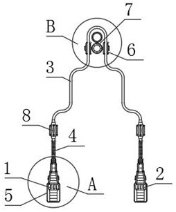
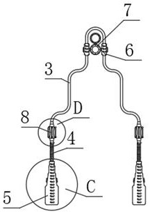
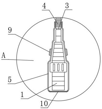
[0024] see Figure 1-7 , the present invention provides the following technical solutions: a photoelectric conversion connector, including the No. 1 connecting terminal 1, the No. 2 connecting terminal 2 and the connecting wire 3, and the No. 3 Fixed connection, the outside of the No. 1 connecting terminal 1 and the No. 2 connecting terminal 2 are covered with a protective sleeve 5, and the upper end of the protective sleeve 5 is located outside the connecting line 3. There is a threaded sleeve 4, and the threaded sleeve 4 is connected to the connecting line. 3 Fixed connection, threaded sleeve 4 and protective sleeve 5 are screwed and connected, the upper end of threaded sleeve 4 is located outside the connection line 3 and fixed with anti-bending sleeve 8, and the outside of anti-bending sleeve 8 is fixed with several anti-bending bars 14, No. 1 The middle position of the upper end of the connecting terminal 1 is provided with a pull ring 7, and both ends of the pull ring 7 ...


PUM


Abstract

The invention belongs to the technical field of connectors, in particular to a photoelectric conversion connector, which includes a No. 1 connection terminal, a No. 2 connection terminal and a connection wire. The No. 1 connection terminal and the No. 2 connection terminal are fixedly connected through the connection wire. The outside of the No. 1 connection end and the No. 2 connection end are covered with a protective sleeve. The upper end of the protective sleeve is located outside the connecting line and a threaded sleeve is provided. The threaded sleeve is fixedly connected with the connecting line, and the threaded sleeve and the protective sleeve are screwed together. , the upper end of the threaded sleeve is located on the outside of the connecting line, and the anti-bending sleeve is fixed on the outside of the anti-bending sleeve, and several anti-bending bars are fixed on the outside of the anti-bending sleeve. The harness barrel is fixed, and the harness barrel is connected with the connecting wire. The harness ring is fixed in the middle of the upper end of the pull ring. When in use, the No. 1 connection end and the No. 2 connection end are wrapped and protected by the protective sleeve. , Simple operation and convenient use.

Description

technical field [0001] The invention belongs to the technical field of connectors, and in particular relates to a photoelectric conversion connector. Background technique [0002] Photoelectric conversion is the process of directly converting solar radiation energy into electrical energy through the photovoltaic effect. The principle of this process is that photons transfer energy to electrons to make them move and form current. Photoelectric conversion devices mainly use the photoelectric effect to convert optical signals into electricity. Signal, since the discovery of the photoelectric effect, photoelectric conversion devices have developed by leaps and bounds. At present, various photoelectric conversion devices have been widely used in all walks of life, and the photoelectric converter and photovoltaic device are usually electrically connected through a photoelectric conversion connector. Connection, the photoelectric conversion connector is an extremely important conne...

Claims


Application Information

Patent Timeline
Patent Type & Authority Patents(China)
IPC IPC(8): H01R31/06H01R13/52H01R13/56H02S40/34H02G3/02
CPCH01R13/521H01R13/562H01R31/06H02G3/02H02S40/34Y02E10/50
Inventor 郑洁
Owner LULIANG UNIV
Learn More