
Insulating insulator cradle front-end fixing ring position adjustable device and working method thereof

A technology of fixing ring and bottle holder, applied in the direction of overhead line/cable equipment, etc., can solve the problems of difficulty in disassembling and assembling insulators, high labor intensity, and the insulator cannot be supported by the bottle holder, so as to improve the replacement work efficiency and reduce the labor intensity. Effect

Pending Publication Date: 2020-06-16
STATE GRID FUJIAN ELECTRIC POWER CO LTD +2
View PDF0 Cites 1 Cited by
  • Summary
  • Abstract
  • Description
  • Claims
  • Application Information

AI Technical Summary

Problems solved by technology

[0002] Porcelain or tempered glass insulators have zero value or are struck by lightning, and often need to be replaced with electricity. In the process of replacing the double-connected insulator string with the ground potential of the big knife clamp, it is necessary to use the insulation operating rod to disassemble the first insulator on the wire side. At this time, the height of the fixing ring at the front end of the insulating bottle holder needs to be exactly at the lower edge of the insulator shed. If the fixing ring is too high, the bottle holder will catch the insulator. If the fixing ring is too low, the bottle holder will not be able to support the insulator. If the fixing ring is too high If the insulator is too low or too low, it is difficult to disassemble and install the insulator. The traditional operation method is to use the trial and error method, which requires the operator on the tower to repeatedly disassemble and assemble the big knife fixture, and manually adjust the front-end fixing ring screw of the insulating bottle holder until the position is right. Large work efficiency and low work efficiency, the purpose of the present invention is to effectively solve this problem and improve the work efficiency of live replacement of double tension insulator strings

Method used


Image

  • Insulating insulator cradle front-end fixing ring position adjustable device and working method thereof
  • Insulating insulator cradle front-end fixing ring position adjustable device and working method thereof
  • Insulating insulator cradle front-end fixing ring position adjustable device and working method thereof

Examples


Embodiment Construction

[0017] In order to make the above-mentioned features and advantages of the present invention more comprehensible, the following specific examples are given in conjunction with the drawings, and detailed descriptions are made as follows.

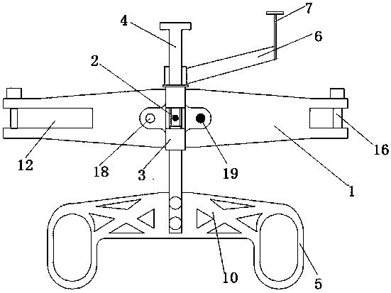
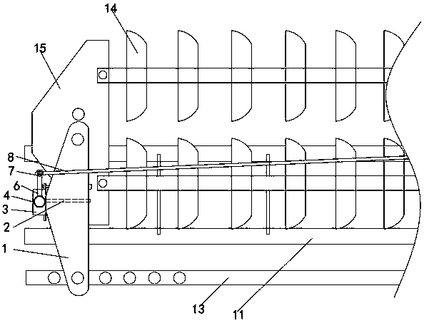
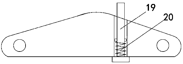
[0018] Such as Figure 1~3 As shown, the device for adjusting the position of the fixed ring at the front end of the insulated bottle holder includes a large knife clamp 1. The middle of the front end of the large knife clamp is connected with a sleeve 3 through a rotating shaft 2 that penetrates back and forth, and a screw 4 is screwed through the top of the sleeve. Adjust the vertical height of the fixing ring 5 at the lower end of the screw. The proximal end of the screw is fixedly provided with an adjusting knob 6 fixedly connected to the top of the outer end of the adjusting knob. The adjusting ring 7 is fixedly attached to the top of the outer end of the adjusting screw. Realize adjustment.

[0019] In the embodiment of the present inventio...


PUM


Abstract

The invention relates to an insulating insulator cradle front-end fixing ring position adjustable device and a working method thereof. The device comprises a broadsword fixture. The middle of the front end of the broadsword fixture is connected with a sleeve through a rotating shaft penetrating front and back. A screw rod is screwed at the top of the sleeve to adjust the vertical height of the fixing ring at the lower end of the screw rod; an adjusting rotary handle is fixedly arranged at the position, close to the upper end, of the screw rod; an adjusting ring is fixedly connected to the topof the outer end of the adjusting rotary handle; an insulating operation rod is used for hooking the adjusting ring to rotate to achieve vertical position adjustment of the fixing ring, so that the position of an insulating insulator cradle inserted into the fixing ring can be adjusted more easily and conveniently, and work efficiency is improved.

Description

Technical field [0001] The invention relates to a device for adjusting the position of a fixed ring at the front end of an insulating bottle holder and a working method thereof. Background technique [0002] When porcelain or tempered glass insulators have zero value or are struck by lightning, they often need to be replaced with electricity. In the process of replacing the double insulator string with a large knife clamp with ground potential, it is necessary to use an insulating operating rod to disassemble and assemble the first insulator on the side of the wire. At this time, the height of the fixed ring at the front end of the insulated bottle holder needs to be exactly at the lower edge of the insulator umbrella. If the fixed ring is too high, the bottle holder will jam the insulator, if the fixed ring is too low, the bottle holder cannot support the insulator, and the fixed ring is too high. It is difficult to disassemble the insulator if it is too low or too low. The trad...

Claims


Application Information

Patent Timeline
Patent Type & Authority Applications(China)
IPC IPC(8): H02G1/02H02G1/04
CPCH02G1/02H02G1/04
Inventor 冯振波吴簪麟蔡金林郑孝干林啸卓晗林信恩徐鹏飞刘行洲廖肇葵张良发
Owner STATE GRID FUJIAN ELECTRIC POWER CO LTD
Learn More