Channel quality estimation method, terminal equipment and network equipment

A technology for channel quality estimation and terminal equipment, which is applied in the field of communication and can solve problems such as low accuracy of estimation results

Active Publication Date: 2020-06-16
中国移动通信集团陕西有限公司 +1
View PDF3 Cites 4 Cited by
  • Summary
  • Abstract
  • Description
  • Claims
  • Application Information

AI Technical Summary

Problems solved by technology

[0004] It can be seen that the current channel quality estimation method has the technical problem of low accuracy of the channel quality estimation result

Method used


Image

  • Channel quality estimation method, terminal equipment and network equipment
  • Channel quality estimation method, terminal equipment and network equipment
  • Channel quality estimation method, terminal equipment and network equipment

Examples


Embodiment Construction

[0056]In order to make the purpose, technical solutions and advantages of the present invention clearer, the following will clearly and completely describe the technical solutions in the embodiments of the present invention with reference to the drawings in the embodiments of the present invention.

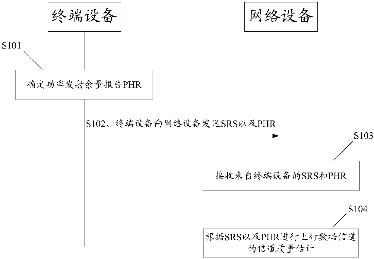
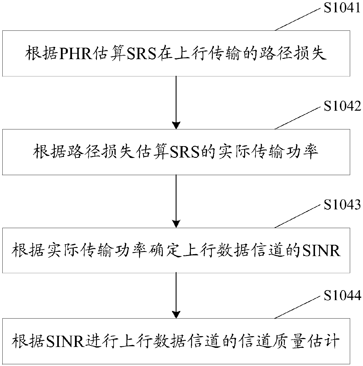
[0057] At present, network devices usually use the SRS sent by the terminal device to estimate the downlink channel state, and the SRS received by the network device is the result of the terminal device's uplink power control, and the terminal device may not send SRS to the network device with full power. For transmission, if the network device ignores the path loss of the SRS in the uplink transmission and directly estimates the channel quality based on the received SRS, then the obtained estimation result of the channel quality is less accurate.

[0058] In view of this, an embodiment of the present invention provides a method for estimating channel quality. In this method, the t...


PUM


Abstract

The invention discloses a channel quality estimation method, terminal equipment and network equipment, which are used for improving the estimation precision of channel quality. The channel quality estimation method comprises the steps: determining a power headroom report (PHR), wherein the PHR is used for indicating a difference value between an actual transmission power and a maximum transmissionpower of a terminal device sending an SRS; and sending an uplink sounding reference signal SRS and the PHR to a network device, so that the network device performs channel quality estimation of an uplink data channel according to the SRS and the PHR.

Description

technical field [0001] The invention relates to the field of communication technology, in particular to a channel quality estimation method, terminal equipment and network equipment. Background technique [0002] In a time division duplex system (Time Division Duplexing, TDD) communication system, a network device such as a base station (Base Station, BS) usually uses an uplink sounding reference signal (Sounding Reference Signal, SRS) to estimate the state of the uplink channel, that is, the terminal equipment For example, a user equipment (User Equipment, UE) sends an SRS to a BS, and the BS realizes quality estimation of an uplink channel according to the SRS, so as to allocate uplink resources. [0003] The SRS received by the BS is based on the result of uplink power control, and the UE may not transmit the SRS at full power when sending the SRS to the BS. If the BS ignores the path loss of the SRS in the uplink transmission and directly estimates the channel quality ba...

Claims


Application Information

Patent Timeline
Patent Type & Authority Applications(China)
IPC IPC(8): H04W24/02H04W24/10H04W52/36
CPCH04W24/02H04W24/10H04W52/365
Inventor 李连本张璐岩贾辉贾磊张阳
Owner 中国移动通信集团陕西有限公司
Why Eureka
Try Eureka