Building sand mixer
A sand mixer and construction technology, applied in the directions of mixers, shake/oscillation/vibration mixers, mixer accessories, etc., can solve the problem of not being able to easily pour out sand materials.
- Summary
- Abstract
- Description
- Claims
- Application Information
AI Technical Summary
Problems solved by technology
Method used
Image
Examples
specific Embodiment approach 1
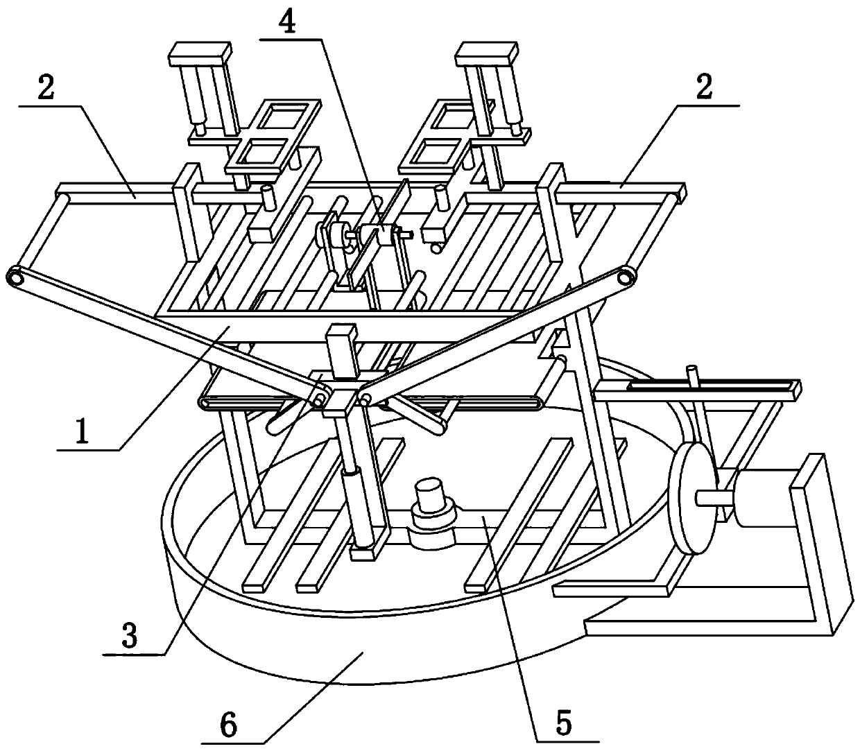
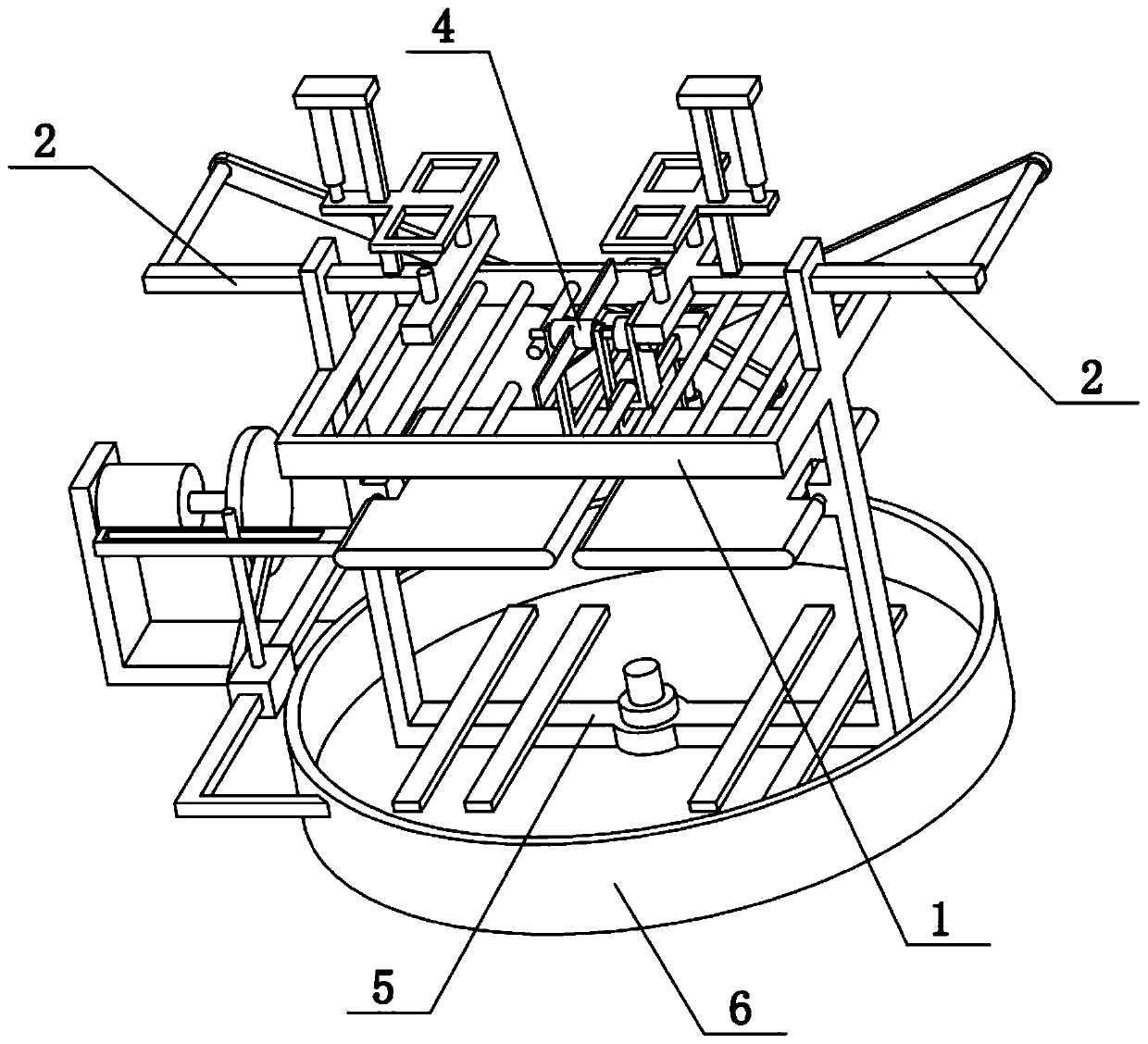
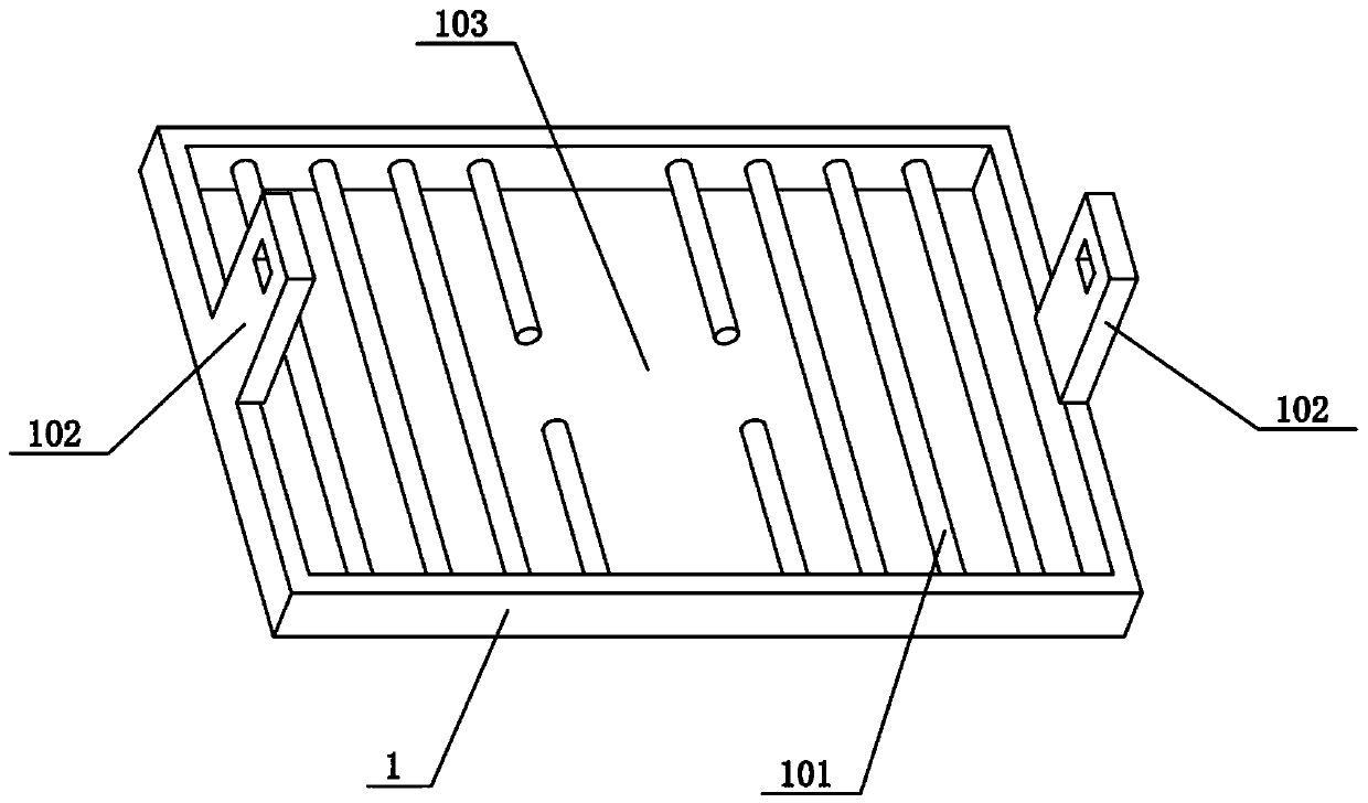
[0029] Combine below Figure 1-8 To illustrate this embodiment, the present invention relates to the field of construction, and more specifically is a construction sand mixer, including a rectangular frame 1, a railing 101, a convex plate 102, a horizontal sliding column 2, a convex pin 201, and a lower seat post 202. The invention can facilitate the pouring of sand from the packaging.
[0030] A plurality of railings 101 are evenly distributed on the rectangular frame 1 from left to right, the left and right ends of the upper side of the rectangular frame 1 are fixedly connected with convex plates 102, and the two convex plates 102 are both horizontally slidably connected with horizontal sliding posts 2 , The inner ends of the two horizontal sliding posts 2 are fixedly connected with a lower seat post 202, and the upper sides of the two lower seat posts 202 are fixedly connected with two convex pins 201. Insert the left end of the packed sand on the two protruding pins 201 at t...
specific Embodiment approach 2
[0032] Combine below Figure 1-8 To illustrate this embodiment, the construction sand mixer further includes a square hole 203, a pressing plate 204, a column 205, an electric push rod I206, and a lifting piece 207. The upper side of the horizontal sliding column 2 is fixedly connected with a column 205, and the column 205 is vertically upward. A lifting piece 207 is slidably connected, and the inner end of the lifting piece 207 is fixedly connected with a pressing plate 204. The front and rear ends of the pressing plate 204 are provided with square holes 203. The two square holes 203 are respectively located above the corresponding two convex pins 201. One end of the rod I206 is fixedly connected to the upper part of the column 205, and the other end of the electric push rod I206 is fixedly connected to the lifting plate 207. When the electric push rod I206 expands and contracts, it can drive the lifting plate 207 and the pressure plate 204 to go up and down, and then can driv...
specific Embodiment approach 3
[0034] Combine below Figure 1-8 To explain this embodiment, the construction sand mixer further includes a fixed shaft 208, a middle sliding block 3, an inclined connecting rod 301, a vertical rail rod 304 and an electric push rod II305. The front side of the rectangular frame 1 is fixedly connected with a vertical rail rod 304 , The vertical rail rod 304 is vertically slidably connected to the middle slider 3, the lower end of the electric push rod II305 is fixedly connected to the lower end of the vertical rail rod 304, the upper end of the electric push rod II305 is fixedly connected to the middle slide 3, two horizontal The outer ends of the sliding column 2 are fixedly connected with fixed shafts 208, the left and right ends of the middle slider 3 are hingedly connected with oblique connecting rods 301, and the other ends of the two oblique connecting rods 301 are respectively rotatably connected to the two fixed shafts 208 . The electric push rod II305 can drive the mid...
PUM
 Abstract
Description
Claims
Application Information
 - R&D
- Intellectual Property
- Life Sciences
- Materials
- Tech Scout
- Unparalleled Data Quality
- Higher Quality Content
- 60% Fewer Hallucinations
Browse by: Latest US Patents, China's latest patents, Technical Efficacy Thesaurus, Application Domain, Technology Topic, Popular Technical Reports.
© 2025 PatSnap. All rights reserved.Legal|Privacy policy|Modern Slavery Act Transparency Statement|Sitemap|About US| Contact US: help@patsnap.com


