
Mechanical device and method for transmitting link induction

A technology of mechanical devices and induction blocks, which is applied in the direction of control devices, molding machines, casting and molding equipment, etc., can solve problems such as equipment misoperation, scratched detection switches, detection switches not in place, etc., to ensure normal operation and production efficiency effect

Inactive Publication Date: 2020-06-19
GUANGXI YUCHAI MASCH CO LTD
View PDF11 Cites 0 Cited by
  • Summary
  • Abstract
  • Description
  • Claims
  • Application Information

AI Technical Summary

Problems solved by technology

As the products to be circulated are pushed from the molding line into the box shifting machine, the distance from the two sides of the claws is not absolutely consistent, which often causes the detection switch on the claws to be out of position and affect production.
[0003] The common treatment methods for the above situation are: 1. Adjust the detection switch close to the surface of the product to be circulated, so that the detection switch is often scratched and the production will be affected
2. Select a detection switch with a relatively large detection distance, but sometimes it does not grasp the position and sense it, which leads to false signals affecting equipment misoperation and affecting production
3. Install detection switches on both sides of the jaws at the same time for induction, take one of the in-position signals to confirm the induction, but sometimes the detection switches on both sides cannot be sensed at the same time, affecting production

Method used


Image

  • Mechanical device and method for transmitting link induction

Examples


Embodiment Construction

[0016] The specific embodiments of the present invention will be described in detail below in conjunction with the accompanying drawings, but it should be understood that the protection scope of the present invention is not limited by the specific embodiments.

[0017] Unless expressly stated otherwise, throughout the specification and claims, the term "comprise" or variations thereof such as "includes" or "includes" and the like will be understood to include the stated elements or constituents, and not Other elements or other components are not excluded.

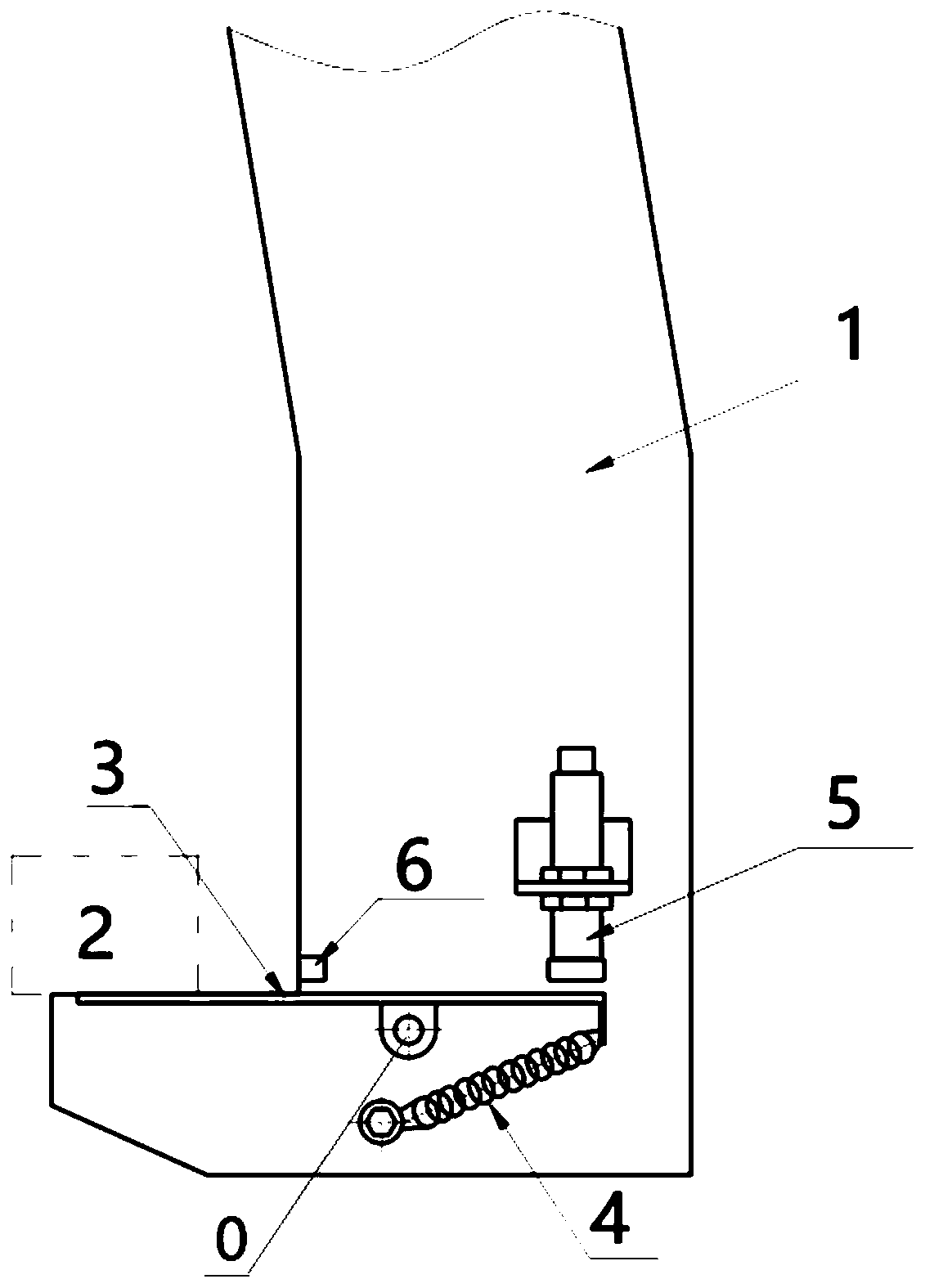
[0018] The mechanical device for transmitting link induction according to the preferred embodiment of the present invention includes: a case shifter and a lever link device. Wherein, the two sides of the case shifter are provided with case shifter jaws 1 for clamping the products 2 to be circulated entering the case shifter. The lever link device is fixedly arranged on the tail end of the claw 1 of the box shifting machine...


PUM


Abstract

The invention discloses a mechanical device for transmitting link induction. The mechanical device comprises a box moving machine, lever link devices and a detection switch, wherein box moving machineclamping jaws are arranged on the two sides of the box moving machine and used for clamping a product to be transferred entering the box moving machine; the lever link devices are fixedly arranged atthe tail ends of the box moving machine clamping jaws and comprise induction blocks, one ends of the induction blocks are close to the product to be transferred and used for receiving pressure from the product to be transferred, and the other ends of the induction blocks are away from the product to be transferred; the detection switch is arranged above the ends, away from the product to be transferred, of the induction blocks; and the two ends of the induction blocks can move up and down around a certain point on the induction blocks, so that when one ends of the induction blocks receive thepressure from the product to be transferred, one of the ends of the induction blocks moves downwards, and the other one of the ends of the induction blocks moves upwards and trigger the detection switch. According to the mechanical device, the phenomenon that production is affected or the detection switch is prone to being scratched due to the fact that induction is not achieved is eliminated while induction signals of the product to be transferred are collected.

Description

technical field [0001] The invention relates to the technical field of mechanical equipment, in particular to a mechanical device and method for transmitting link induction. Background technique [0002] At present, in the molding line of foundry enterprises, the claws of the box shifting machine clamp the products to be circulated in place, and the method of directly installing the induction products to be circulated on the claws is often used. Since the position of the products to be circulated is not absolutely consistent from the two sides of the jaws when they are pushed from the molding line into the box shifter, the detection switch on the jaws often fails to sense properly and affects production. [0003] The common treatment methods for the above situation are: 1. Adjust the detection switch close to the surface of the product to be circulated, so that the detection switch is often scratched and affects production. 2. Choose a detection switch with a relatively lar...

Claims


Application Information

Patent Timeline
IPC IPC(8): B22C11/02B22C19/04
CPCB22C11/02B22C19/04
Inventor 谢桂才李秋红梁旭
Owner GUANGXI YUCHAI MASCH CO LTD
Learn More