Perforating device for electric power fitting

A technology of punching device and power fittings, applied in positioning devices, manufacturing tools, boring/drilling and other directions, can solve problems such as accurate positioning, line failure, product unqualified, etc., to ensure punching quality and accurate punching. , the effect of convenient operation

Inactive Publication Date: 2020-06-19
青岛正为能源科技有限公司
View PDF0 Cites 2 Cited by
  • Summary
  • Abstract
  • Description
  • Claims
  • Application Information

AI Technical Summary

Problems solved by technology

[0002] Iron or aluminum metal accessories widely used in transmission wires are collectively referred to as fittings. Most of the fittings need to bear a large pulling force during operation, and some of them must also ensure good electrical contact at the same time. or the safety of the tower, even if one is damaged, it may cause line failure
[0003] When drilling metal tools, it needs to be positioned to ensure the accuracy of the drilling position. The existing drilling tooling generally needs to be used with a workbench, which is inconvenient for accurate positioning of the drilling position of the metal tools, and the drilling efficiency Low, it is easy to cause unqualified products when drilling

Method used


Image

  • Perforating device for electric power fitting
  • Perforating device for electric power fitting
  • Perforating device for electric power fitting

Examples


Embodiment 1

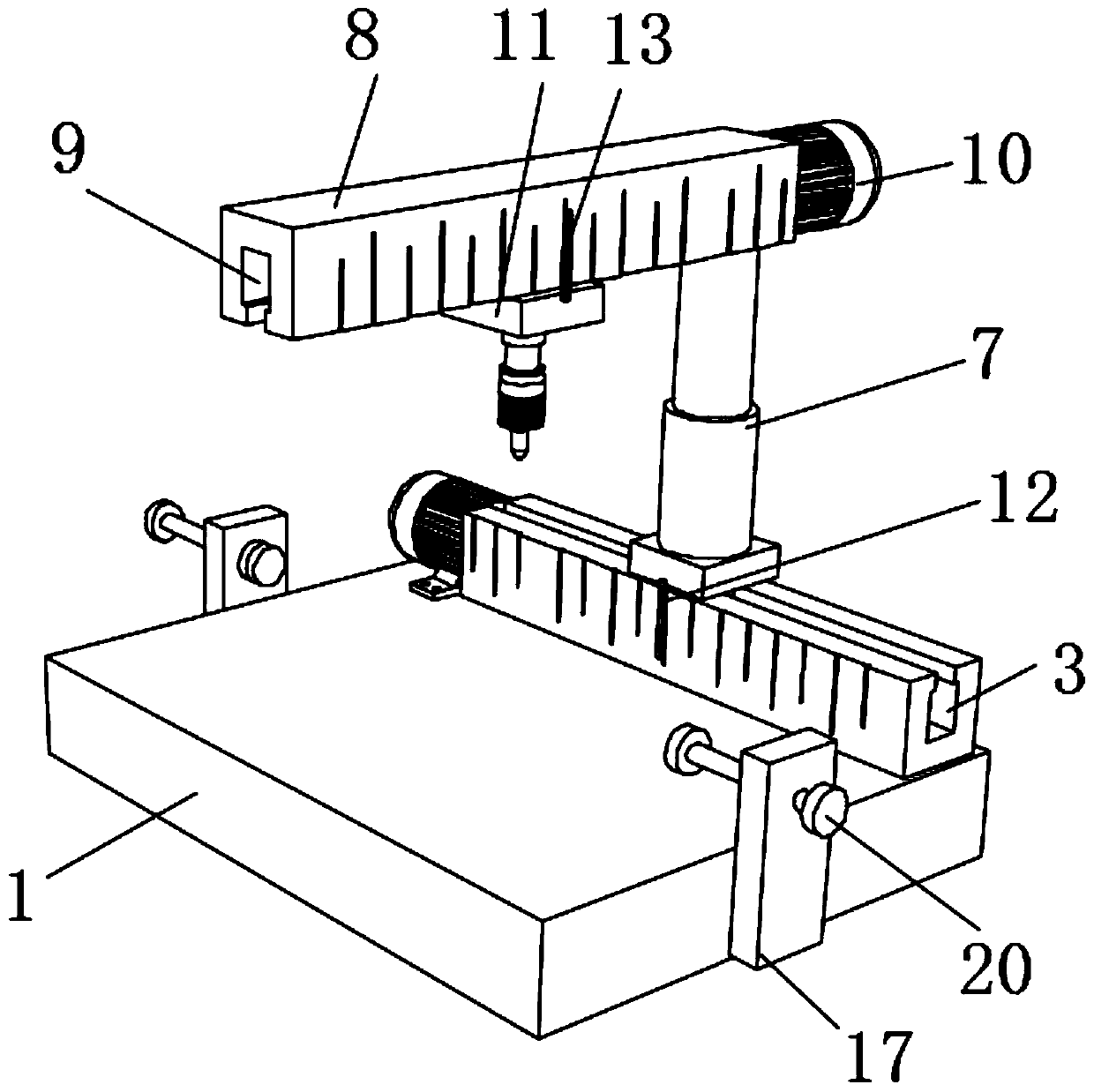
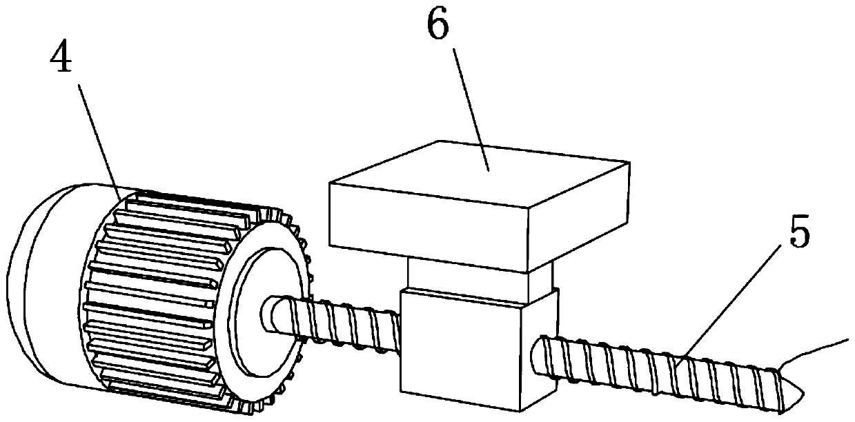
[0025] refer to Figure 1-3 , a punching device for electric power fittings, comprising a base 1 fixedly connected with a first slide rail 2 on one side of the upper end, the upper end of the first slide rail 2 is dug with a first chute 3, and the first chute 3 is slidably connected There is a first slider matching it, and a screw hole is drilled on the first slider, the end of the first slide rail 2 is provided with a first motor 4, and the first motor 4 is fixedly connected to the upper end surface of the base 1, the first The power output end of the motor 4 is connected with a screw rod 5, and the screw rod 5 is threadedly connected with the screw hole on the first slider, and the upper end of the first slider extends to the upper side of the first chute 3 and is fixedly connected with the first fixed seat 6, The upper end of the first fixed base 6 is fixedly connected with the first electric telescopic rod 7, the upper end of the first electric telescopic rod 7 is fixedly ...

Embodiment 2

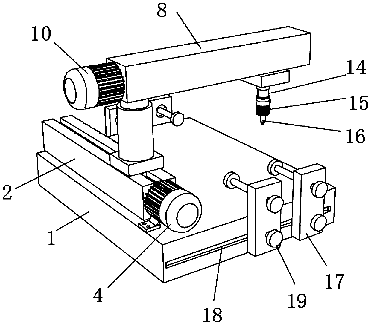
[0031] refer to figure 2 , a punching device for electric power fittings. Compared with Embodiment 1, this embodiment has a locking screw hole dug on the clamping seat 17, and an I-shaped locking member 19 is threadedly connected to the locking screw hole. The side end of the base 1 is dug with a third chute 18 matching the end of the I-shaped locking member 19, and there are multiple pairs of clamping parts.

[0032] Working principle: The position of the clamping part can be adjusted according to the size of the hardware, that is, loosen the I-shaped locking part 19, then push the clamping seat 17 to the required position along the third chute 18, and tighten the I-shaped locking part 19 That is, a plurality of clamping parts can make the fixing of the hardware more stable.


PUM


Abstract

The invention discloses a perforating device for an electric power fitting. The perforating device for the electric power fitting comprises a base, wherein one side of the upper end of the base is fixedly connected with a first sliding rail; a first chute is formed in the upper end of the first sliding rail; the interior of the first chute is connected, in a sliding manner, with a first sliding block which is matched with the first chute; a screw hole is formed in the first sliding block; a first motor is arranged at an end part of the first sliding rail; a power output end of the first motoris connected with a screw rod; the screw rod is in threaded connection with the screw hole in the first sliding block; the upper end of the first sliding block extends to the upper side of the first chute and is fixedly connected with a first fixed seat; the upper end of the first fixed seat is fixedly connected with a first electric telescopic rod; the upper end of the first electric telescopic rod is fixedly connected with a second sliding rail; scale marks are respectively marked at the side ends of the first sliding rail and the second sliding rail; and the side ends of the first fixed seat and a second fixed seat are respectively and fixedly connected with a transverse pointer and a longitudinal pointer. The perforating device for the electric power fitting is simple in structure andconvenient to operate, and can realize accurate perforating of fitting so as to ensure perforating quality.

Description

technical field [0001] The invention relates to the technical field of punching devices, in particular to a punching device for electric fittings. Background technique [0002] Iron or aluminum metal accessories widely used in transmission wires are collectively referred to as fittings. Most of the fittings need to bear a large pulling force during operation, and some of them must also ensure good electrical contact at the same time. Or the safety of the tower, even if one is damaged, it may cause line failure. [0003] When drilling metal tools, it needs to be positioned to ensure the accuracy of the drilling position. The existing drilling tooling generally needs to be used with a workbench, which is inconvenient for accurate positioning of the drilling position of the metal tools, and the drilling efficiency Low, it is easy to cause unqualified products when drilling. Therefore, it is necessary to design the punching tool for electric fittings on demand to ensure the qu...

Claims


Application Information

Patent Timeline
Patent Type & Authority Applications(China)
IPC IPC(8): B23B41/00B23Q1/25B23Q17/22B23Q3/06
CPCB23B41/00B23Q1/25B23Q3/062B23Q17/22
Inventor 李志强尹翠萍韩晓鹏张真真李佳泽
Owner 青岛正为能源科技有限公司
Why Eureka
Try Eureka