Automatic pipe fitting assembly mechanism

A technology for automatic assembly and pipe fittings, applied in metal processing, metal processing equipment, manufacturing tools, etc., can solve the problems of inability to meet production and use, reduce the degree of automation of pipe fitting assembly, and difficult to ensure the efficiency and quality of pipe fitting press-fitting processing, and achieve structural Reasonable design and the effect of improving the degree of automation

Active Publication Date: 2020-06-19
SUZHOU JUHUIBANG NEW MATERIAL TECH CO LTD
View PDF5 Cites 8 Cited by
  • Summary
  • Abstract
  • Description
  • Claims
  • Application Information

AI Technical Summary

Problems solved by technology

The existing pipe fitting assembly equipment is difficult to realize pipe fitting assembly and processing efficiently and smoothly. No matter it is the transmission and feeding of pipe fittings before assembly, the assembly process of pipe fittings and the unloading of workpieces after assembly, workers need to manually operate the workpiece, which reduces the automation of pipe fitting assembly. To a certain extent, in the process of assembling pipe fittings, the existing pipe fitting assembly equipment can only realize the press-fit processing of pipe fittings and single components, and cannot continuously assemble the pipe fittings with multiple components during the transfer process according to the needs of pipe fitting assembly, which is difficult To ensure the efficiency and quality of pipe fitting press-fitting processing, it cannot meet the needs of production and use

Method used


Image

  • Automatic pipe fitting assembly mechanism
  • Automatic pipe fitting assembly mechanism
  • Automatic pipe fitting assembly mechanism

Examples


Embodiment Construction

[0028] In order to further describe the present invention, a specific implementation of an automatic assembly mechanism for pipe fittings will be further described below in conjunction with the accompanying drawings. The following examples are explanations of the present invention and the present invention is not limited to the following examples.

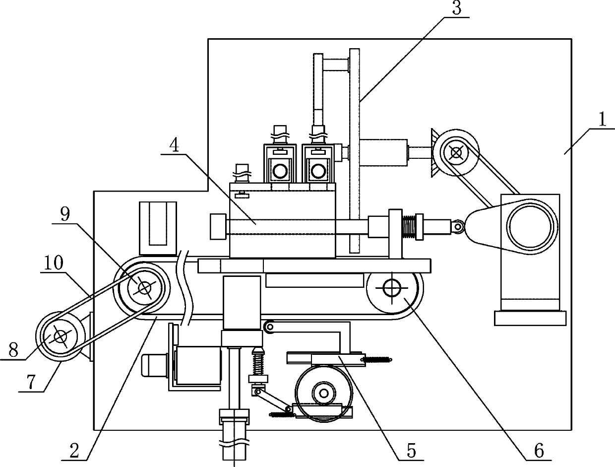
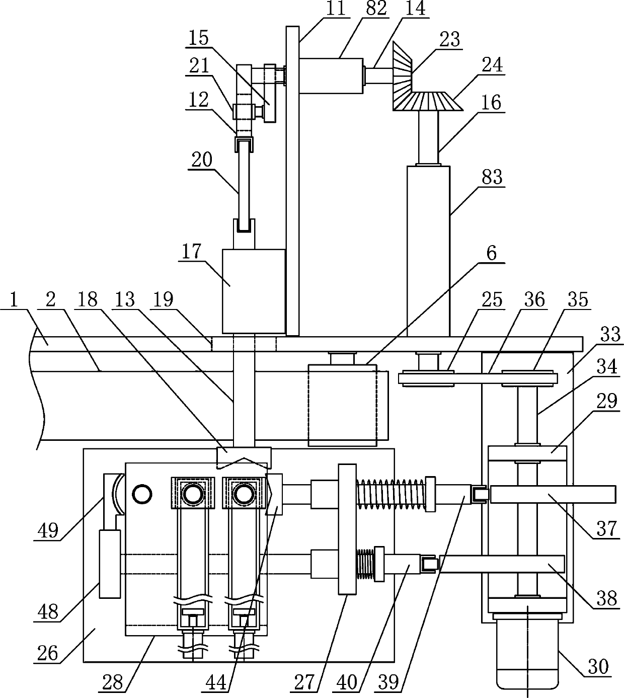
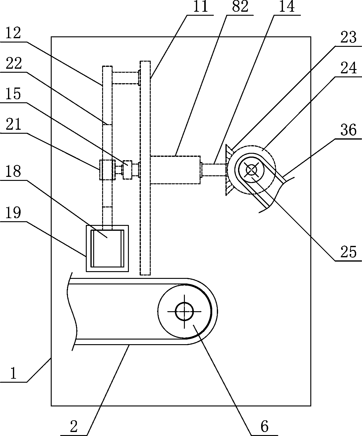
[0029] Such as figure 1 and figure 2 As shown, an automatic assembly mechanism for pipe fittings of the present invention includes a workpiece transmission bracket 1, a workpiece conveying belt 2, a workpiece pushing mechanism 3, a workpiece pressing mechanism 4 and a workpiece unloading mechanism 5, and the workpiece conveying belt 2 is horizontally arranged on the workpiece On the lower side of the conveying bracket 1, the workpiece pushing mechanism 3 and the workpiece pressing mechanism 4 are respectively arranged on the workpiece conveying bracket 1 on both sides of the workpiece conveying belt 2, and the workpiece unloading ...


PUM


Abstract

The invention discloses an automatic pipe fitting assembly mechanism, and belongs to the field of workpiece production and mechanical equipment. A workpiece pushing mechanism and a workpiece pressingmechanism of the mechanism are separately arranged on workpiece conveying supports on the two sides of a workpiece conveying belt, a workpiece discharging mechanism is arranged on the workpiece conveying support at the lower side of the workpiece pressing mechanism, a reciprocating translation push rod is slidably arranged on a push rod guide supporting base in the horizontal direction, a reciprocating material pushing connection rod is arranged between the reciprocating translation push rod and the lower end of a material pushing reciprocating swing rod, a workpiece pressing support is horizontally and fixedly arranged on the upper side of a pressing support plate, and the output end of a workpiece lifting cylinder is fixedly connected with the lower side of a workpiece lifting support plate. According to the mechanism, the structural design is reasonable, sequential continuous pressing machining of a plurality of assemblies can be efficiently and stably realized during a transferringprocess of pipe fittings, the pipe fitting can be conveniently and smoothly discharged and guided, a workpiece machining automation degree is improved, and the requirement for production and use is met.

Description

technical field [0001] The invention belongs to the field of workpiece production and processing machinery, in particular to an automatic assembly mechanism for pipe fittings, which is mainly used in the field of continuous transmission, assembly and processing of pipe fittings. Background technique [0002] Mechanical workpieces are inseparable individual parts that make up machinery and machines. It plays an important role in the automation industry. Mechanical workpieces include the connection of parts, supporting parts, lubricating lubrication systems and seals. Components, components of the transmission system that transmit motion and energy, mechanical workpieces can be divided into shaft sleeve workpieces and disc cover workpieces according to their shapes, pipe fittings are the main shaft sleeve workpieces, pipe fittings are workpieces with cylindrical structure, pipe fittings There are many types, and different pipe fittings use different materials. The quality of t...

Claims


Application Information

Patent Timeline
Patent Type & Authority Applications(China)
IPC IPC(8): B23P19/027B23P19/00
CPCB23P19/001B23P19/007B23P19/027
Inventor 费建国
Owner SUZHOU JUHUIBANG NEW MATERIAL TECH CO LTD
Why Eureka
Try Eureka