
A magnetic puller

A material puller and magnetic technology, which is applied in metal processing equipment, maintenance and safety accessories, metal processing machinery parts, etc., can solve the problems of large footprint, low economy, large investment, etc., and achieve long overall life and magnetic Strong suction, not easy to wear

Active Publication Date: 2021-08-06
HUBEI JIANGSHAN HEAVY IND
View PDF8 Cites 0 Cited by
  • Summary
  • Abstract
  • Description
  • Claims
  • Application Information

AI Technical Summary

Problems solved by technology

However, the automatic feeding device outside the machine and industrial robots require a large investment, high cost, long cycle, and large floor space. It is not economical to process small and medium batches of workpieces.

Method used


Image

  • A magnetic puller
  • A magnetic puller
  • A magnetic puller

Examples


Embodiment Construction

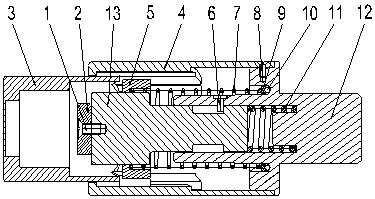
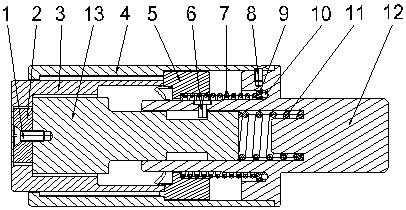
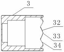
[0031] Figure 1-2 Among them, the fixed strong magnet of slide shaft 13 front ends is installed in the body hole, and spring 11 is arranged at the bottom of the hole, and is fixed in the body hole by three pins 6 of circumferential distribution, and can move axially. There are 4 protruding keys 2 31 on the right end outer circle of shield 3, cooperate with the groove of sleeve 4 inwalls, can move along its axial direction, distance 45 millimeters. There are 8 evenly distributed annular teeth on the right end surface of the shield 3 . There are 4 unreasonable straight grooves on the inner wall of the sleeve 4, which cooperate with the convex key 2 31 on the shield 3, and the ribs 43 positioned on the inner wall of the sleeve 4 are formed between two adjacent straight grooves, and each rib 43 end surface has 2 a helical tooth. The toothed wheel 5 is hollow and is set on the sliding shaft 13. There are 4 protruding keys on the outer circle which match with the straight groove ...


PUM


Abstract

A magnetic material puller, comprising an elastic telescopic shaft, a powerful magnet is fixed at the front end of the elastic telescopic shaft; a cylindrical shield, the rear end of the outer circle of the shield has n convex keys 2 evenly distributed around it, and the rear end of the shield is 2n The teeth are connected to form a ring-shaped tooth part; the tooth wheel has a central hole in the middle of the tooth wheel, and n convex keys are evenly distributed around the outer circle of the tooth wheel, and the left end of the convex key 1 is a one-way helical tooth; the sleeve, the inner wall of the sleeve is a step Shaped structure, including a thick tube part at the front end and a thin tube part at the rear end, the inner wall of the thick tube part has n straight grooves uniformly distributed from the front end to the rear end, and a rib is formed between two adjacent straight grooves, each There are two ratchet parts at the end of the convex rib; the front end of the elastic telescopic shaft is covered with a shield, the center hole of the cone is set outside the elastic telescopic shaft at the rear of the shield, and a spring is arranged between the cone and the elastic telescopic shaft. The sleeve is sheathed outside the shield and the cone, and the rear end of the sleeve is fixedly mounted on the elastic telescopic shaft. The invention has safe and reliable action, firm suction, no loosening during the process, and can accurately control the length of the pulled material.

Description

technical field [0001] The invention belongs to the field of metal cutting and processing, and in particular relates to an automatic material pulling device used in a turning center. Background technique [0002] At present, when CNC lathes are processing small and medium batches of small and medium-sized parts, if there is no automatic pulling mechanism and the program running time is short, the operator will be bound to a single machine position, loading and unloading workpieces continuously, and it is impossible to carry out one-person double-machine operation , and the action of the worker is single, and the labor intensity is high. The automatic puller can realize the long-term automatic and unmanned continuous operation of the CNC lathe. The existing mechanical puller in the machine has a small number of claws, which belong to point contact, easy to loosen, and the adjustment range is limited. During the pulling process, it is hard to pull out and insert along the axi...

Claims


Application Information

Patent Timeline
Patent Type & Authority Patents(China)
IPC IPC(8): B23Q7/00B23Q11/08
CPCB23Q7/00B23Q11/08
Inventor 周德民孟繁胜张甲涛张伟罗聪慧
Owner HUBEI JIANGSHAN HEAVY IND
Learn More