A conveniently controlled conveying device for mechanical processing

A technology of mechanical processing and conveying device, applied in the field of mechanical processing, can solve the problems of not being able to control the conveying and stopping of the conveying device according to the needs, spending a lot of waiting time, and reducing the transportation efficiency.

Active Publication Date: 2021-03-26
浙江同发塑机有限公司
View PDF8 Cites 0 Cited by
  • Summary
  • Abstract
  • Description
  • Claims
  • Application Information

AI Technical Summary

Problems solved by technology

In the process of mechanical processing, it is necessary to use the conveying device to convey the mechanical parts that need to be processed and processed. The existing conveying device cannot control the conveying and stopping of the conveying device according to the needs during the conveying process. The existing device used In the process of use, due to the regular reciprocating movement of the conveying device, it is impossible to realize the parts that need to be processed and processed on the device before being transported. Therefore, in the process of processing and transporting mechanical parts, it is necessary to The transportation can only be carried out after the transportation device moves to the position where the mechanical parts need to be placed, so the transportation efficiency is greatly reduced, and it takes a lot of waiting time during the transportation process, and it cannot be transported at any time according to the transportation needs

Method used


Image

  • A conveniently controlled conveying device for mechanical processing
  • A conveniently controlled conveying device for mechanical processing
  • A conveniently controlled conveying device for mechanical processing

Examples


Embodiment Construction

[0021] The following will clearly and completely describe the technical solutions in the embodiments of the present invention with reference to the accompanying drawings in the embodiments of the present invention. Obviously, the described embodiments are only some, not all, embodiments of the present invention. Based on the embodiments of the present invention, all other embodiments obtained by persons of ordinary skill in the art without making creative efforts belong to the protection scope of the present invention.

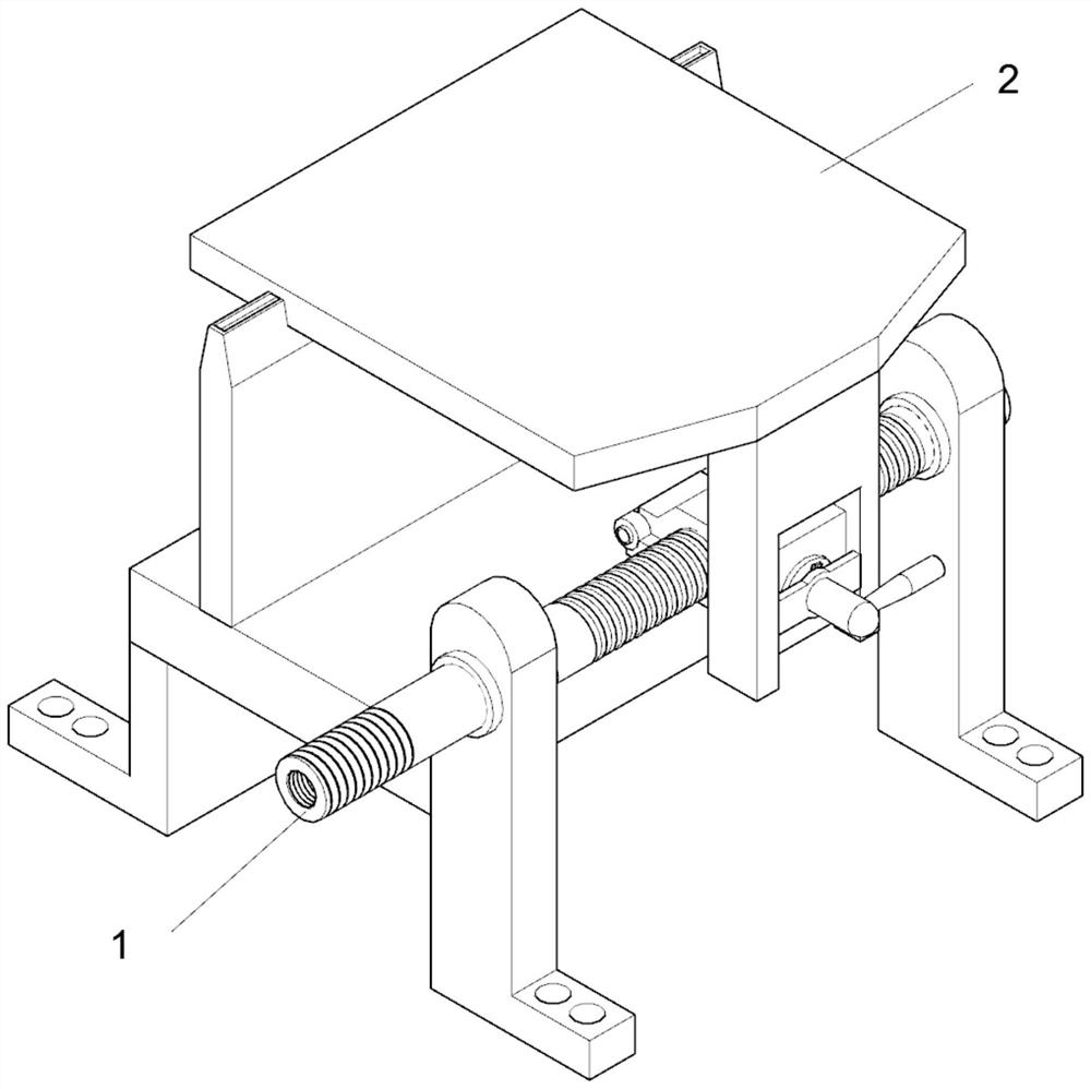
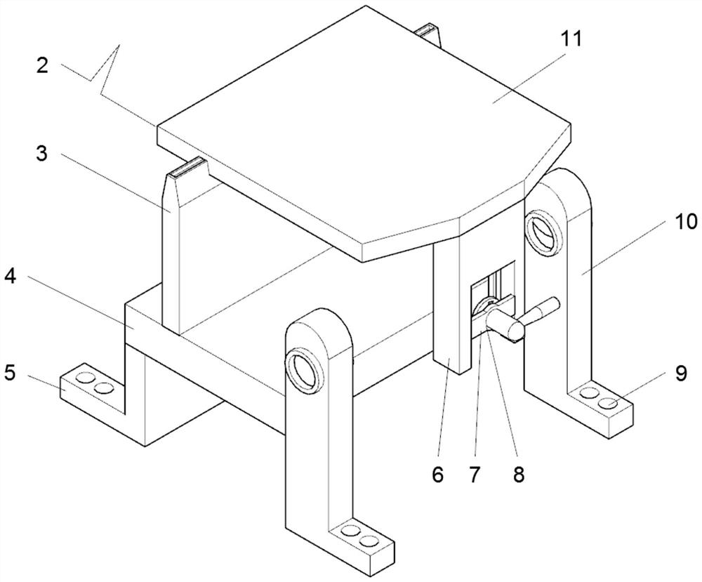
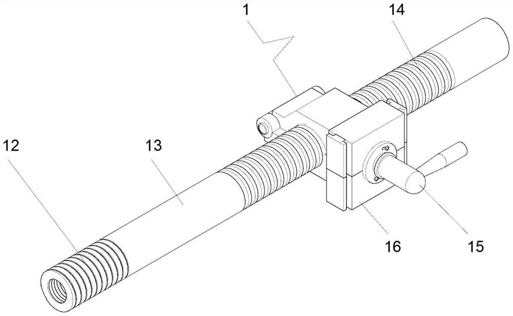
[0022] see Figure 1-6 , an embodiment provided by the present invention: a conveniently controlled conveying device for mechanical processing, including a drive control device 1, a drive connecting rod 13 is installed in the drive control device 1, and a connecting thread 12 is provided at the front end of the drive connecting rod 13 , the driving connecting rod 13 is provided with a conveying thread 14, an adjustable driving member 16 is mounted on the conve...


PUM


Abstract

The invention discloses a machining conveying device convenient to control. The machining conveying device comprises a drive control device. A drive connecting rod is mounted in the drive control device. A connecting thread is formed at the front end of the drive connecting rod. A conveying thread is formed on the drive connecting rod. An adjustable drive part is mounted on the conveying thread ina threaded rotating manner. A second adjusting part is mounted in the adjustable drive part. A second sliding bock is fixedly connected to the front end of the second adjusting part. A second adjusting column is fixedly mounted on the front end face of the second sliding bock. A connecting column is fixedly connected to the end, away from the second sliding block, of the second adjusting part. Aconnecting shaft is fixedly mounted in an adjusting device. In the use process, mechanical components needing to be conveyed can be rapidly and conveniently placed on the device to be conveyed, in theconveying process, mechanical components can be rapidly placed conveniently, device moving can be controlled conveniently and rapidly, and the device can be controlled in real time.

Description

technical field [0001] The invention relates to the technical field of mechanical processing, in particular to a conveniently controlled conveying device for mechanical processing. Background technique [0002] Machining refers to the process of changing the shape or performance of workpieces through mechanical equipment. According to the difference in processing method, it can be divided into cutting processing and pressure processing. In the process of mechanical processing, it is necessary to use the conveying device to convey the mechanical parts that need to be processed and processed. The existing conveying device cannot control the conveying and stopping of the conveying device according to the needs during the conveying process. The existing device used In the process of use, due to the regular reciprocating movement of the conveying device, it is impossible to realize the parts that need to be processed and processed on the device before being transported. Therefor...

Claims


Application Information

Patent Timeline
Patent Type & Authority Patents(China)
IPC IPC(8): B65G47/74B23Q7/00
CPCB23Q7/00B65G47/74
Inventor 郑鹏庆
Owner 浙江同发塑机有限公司
Why Eureka
Try Eureka