
Continuous construction method for aluminum alloy template used for comprehensive pipe rack

A technology of aluminum alloy formwork and integrated pipe gallery, which is applied in artificial islands, water conservancy projects, infrastructure projects, etc., can solve the problems of poor forming effect, mold expansion, and low turnover times.

Active Publication Date: 2020-06-19
BEIJING MUNICIPAL ROAD & BRIDGE +1
View PDF7 Cites 5 Cited by
  • Summary
  • Abstract
  • Description
  • Claims
  • Application Information

AI Technical Summary

Problems solved by technology

Among them, the wooden formwork requires more supporting components; it takes a long time to set up and remove the formwork, and the turnover efficiency is low; the erection, transfer and disassembly of the formwork all require more labor costs; Phenomena such as slurry leakage and mold expansion are prone to occur, resulting in poor molding effect after mold removal, and common quality problems such as wrong platform, honeycomb, and pockmarked surface are prone to occur
Wood-plastic molds also require more labor costs and supporting components; the turnover efficiency is low; and their rigidity is poor, and mold expansion is prone to occur during pouring, and the molding effect is average
Due to the outstanding turnover characteristics and good construction quality of aluminum formwork, it has broad market prospects in the application of large-scale pipe gallery standard section structures, but aluminum formwork also requires more labor; the turnover speed is slightly faster than wooden formwork, but the overall efficiency is not good. high

Method used


Image

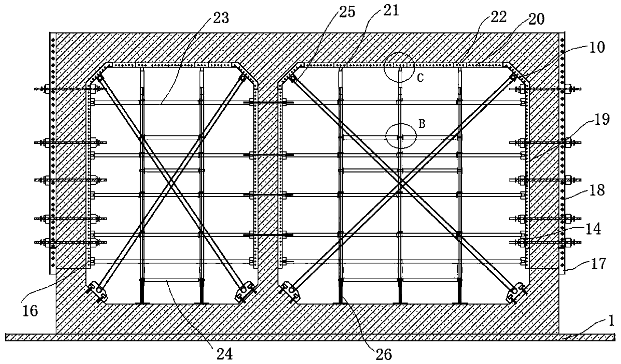
  • Continuous construction method for aluminum alloy template used for comprehensive pipe rack
  • Continuous construction method for aluminum alloy template used for comprehensive pipe rack
  • Continuous construction method for aluminum alloy template used for comprehensive pipe rack

Examples


Embodiment Construction

[0074] In order to make the purpose, technical solutions and advantages of the embodiments of the present invention clearer, the technical solutions in the embodiments of the present invention will be clearly and completely described below in conjunction with the drawings in the embodiments of the present invention. Obviously, the described embodiments It is a part of embodiments of the present invention, but not all embodiments. The components of the embodiments of the invention generally described and illustrated in the figures herein may be arranged and designed in a variety of different configurations.

[0075] Accordingly, the following detailed description of the embodiments of the invention provided in the accompanying drawings is not intended to limit the scope of the claimed invention, but merely represents selected embodiments of the invention. Based on the embodiments of the present invention, all other embodiments obtained by persons of ordinary skill in the art wi...


PUM


Abstract

The invention specifically provides a continuous construction method for an aluminum alloy template used for a comprehensive pipe rack. Second-time pouring construction of a first-section comprehensive pipe rack and first-time pouring construction of a second-joint comprehensive pipe rack are conducted at the same time, the construction speed is increased, the construction period is shortened, anda bottom die structure demounted from the first-section comprehensive pipe rack is used for conducting construction of a bottom plate and a guide wall of the second-joint comprehensive pipe rack while a wall body and a top plate aluminum alloy template of the first-section comprehensive pipe rack are installed; when the strength of concrete reaches 1.2 Mpa, an inner wall template and an outer wall template are demounted and are conveyed to a next construction section; and when concrete pouring is completed and the strength reaches 50%-75%, a top face template is demounted, a top support and longitudinal supporting rods are reserved, after the strength of the concrete reaches 100%, demounting is conducted, meanwhile, construction of a bottom plate and a guide wall of the second-joint comprehensive pipe rack is completed, the demounted wall body and the top plate aluminum alloy template are used for continuously conducting construction of a wall body and a top plate of the second-section comprehensive pipe rack, and therefore continuous cyclic work is achieved.

Description

technical field [0001] The invention relates to the construction of an underground comprehensive utility gallery, in particular to a continuous construction method of an aluminum alloy formwork used for the comprehensive utility gallery. Background technique [0002] As a construction facility built underground in the city to accommodate urban engineering pipelines, the pipe gallery is an important part of urban infrastructure construction. The comprehensive pipe gallery, that is, a common ditch and a common pipeline, is a tunnel space built underground in the city. Communication, gas, heating, water supply and drainage and other engineering pipelines are integrated to achieve unified planning. [0003] At present, two pourings are usually used in the construction of the pipe gallery, that is, from the bottom to the top, the lower part of the guide wall is poured first, and then the remaining part is poured. When the guide wall is poured, the outer formwork is mostly made...

Claims


Application Information

Patent Timeline
IPC IPC(8): E02D29/045
CPCE02D29/10
Inventor 闫云飞赵福勇李凌宜杨珂崔明英张小航刘明李笑天王润涛冯争张国磊姚峰王小转李栋
Owner BEIJING MUNICIPAL ROAD & BRIDGE
Learn More