
Transformer fault diagnosis method and device based on vibration striples

A technology of transformer fault and diagnosis method, applied in the direction of measuring devices, instruments, measuring electrical variables, etc., can solve problems such as inaccurate fault monitoring, and achieve the effect of avoiding misjudgment

Inactive Publication Date: 2020-06-19
SHENZHEN POWER SUPPLY BUREAU
View PDF2 Cites 2 Cited by
  • Summary
  • Abstract
  • Description
  • Claims
  • Application Information

AI Technical Summary

Problems solved by technology

[0004] Based on this, it is necessary to provide a vibration-based transformer fault diagnosis method and device for the problem of inaccurate fault monitoring existing in the current single-point measurement method

Method used


Image

  • Transformer fault diagnosis method and device based on vibration striples
  • Transformer fault diagnosis method and device based on vibration striples
  • Transformer fault diagnosis method and device based on vibration striples

Examples


Embodiment Construction

[0043] In order to make the above objects, features and advantages of the present invention more comprehensible, specific implementations of the present invention will be described in detail below in conjunction with the accompanying drawings. In the following description, numerous specific details are set forth in order to provide a thorough understanding of the present invention. However, the present invention can be implemented in many other ways different from those described here, and those skilled in the art can make similar improvements without departing from the connotation of the present invention, so the present invention is not limited by the specific implementations disclosed below.

[0044] Unless otherwise defined, all technical and scientific terms used herein have the same meaning as commonly understood by one of ordinary skill in the technical field of the invention. The terms used herein in the description of the present invention are for the purpose of descr...


PUM


Abstract

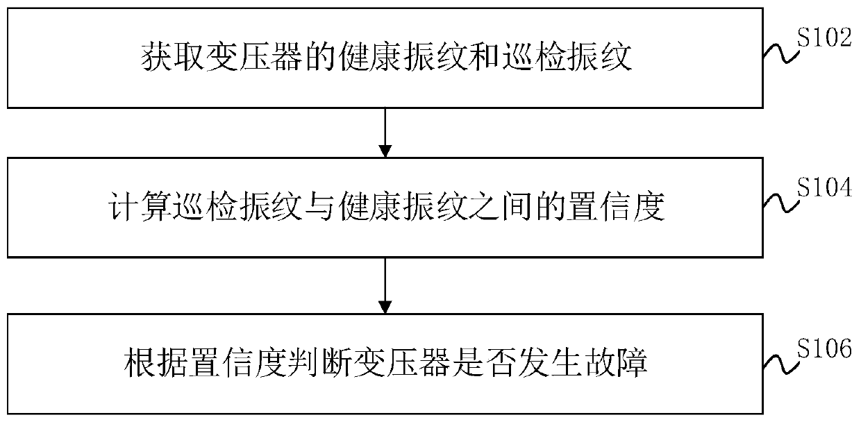
The invention relates to a transformer fault diagnosis method and device based on vibration stripes. The transformer fault diagnosis method based on vibration stripes comprises the steps of acquiringhealthy vibration stripes and inspection vibration stripes of a transformer; calculating the confidence coefficient between the inspection vibration lines and the health vibration lines; and judging whether a transformer fails or not according to the confidence. Misjudgment caused by magnitude change due to load change can be effectively avoided, so that accurate, stable and reliable monitoring ofthe transformer is realized.

Description

technical field [0001] The invention relates to the technical field of fault diagnosis, in particular to a vibration-mark-based transformer fault diagnosis method and device. Background technique [0002] Power equipment is one of the most important devices in modern industrial production. Once the equipment fails, it may cause the entire system to be paralyzed and cause major economic losses. In recent years, more and more attention has been paid to condition monitoring in power systems, and many condition monitoring methods have been proposed for different power equipment in power systems, such as vibration analysis, gas in oil analysis and partial discharge detection. [0003] For the condition monitoring of transformers, since the surface vibration signal of the transformer oil tank is closely related to the mechanical condition of its internal winding and iron core, the measurement and characteristic analysis of the surface vibration signal of the transformer oil tank i...

Claims


Application Information

Patent Timeline
Patent Type & Authority Applications(China)
IPC IPC(8): G01R31/00G01H17/00
CPCG01H17/00G01R31/00
Inventor 余鹏李艳梁兆杰王枭
Owner SHENZHEN POWER SUPPLY BUREAU
Learn More