Water tank water inlet multi-water-pipe energy dissipation and flow stabilization system and operation method

A technology of water inlet and water tank, which is applied in the field of multi-pipe energy dissipation and steady flow system at the water inlet of the water tank, which can solve the problems of short straight section distance, unstable flow state of water inlet and outlet, long section of unstable water flow at the water inlet, etc. , to achieve the effect of improving efficiency and stability, simple working principle, and reducing turbulent kinetic energy

Inactive Publication Date: 2020-06-19
HOHAI UNIV
View PDF4 Cites 0 Cited by
  • Summary
  • Abstract
  • Description
  • Claims
  • Application Information

AI Technical Summary

Problems solved by technology

[0002] At present, due to the limited experimental sites in colleges and universities, there is basically no condition to build experimental water tanks with long straight-line distances, especially for water flow research experimental water tanks for teaching. The unstable flow state of the water flow makes the effective working distance of the experimental water tank very limited. In order to improve the use effect of the water tank, necessary flow stabilization treatment must be taken at the water inlet, and the severe water turbulence caused by the difference in water head and the excessive instantaneous flow rate must be taken. motion, that is, it is necessary to take effective measures to eliminate or reduce the turbulent kinetic energy not required for the experiment
[0003] At present, the treatment method for the unstable water flow of the water inlet tank is usually to use geotechnical mats to dissipate energy, and then flow into the working water tank after standing still in the rectangular water tank, resulting in too long section of unstable water flow at the water inlet; In the case of water supply and the working range of the experimental tank is only a dozen meters, if the energy dissipation facilities at the inlet and outlet cannot play a significant role in stabilizing the flow, it will reduce the effective length of the experimental tank, greatly reducing the experimental efficiency and stability

Method used


Image

  • Water tank water inlet multi-water-pipe energy dissipation and flow stabilization system and operation method
  • Water tank water inlet multi-water-pipe energy dissipation and flow stabilization system and operation method
  • Water tank water inlet multi-water-pipe energy dissipation and flow stabilization system and operation method

Examples


Embodiment 1

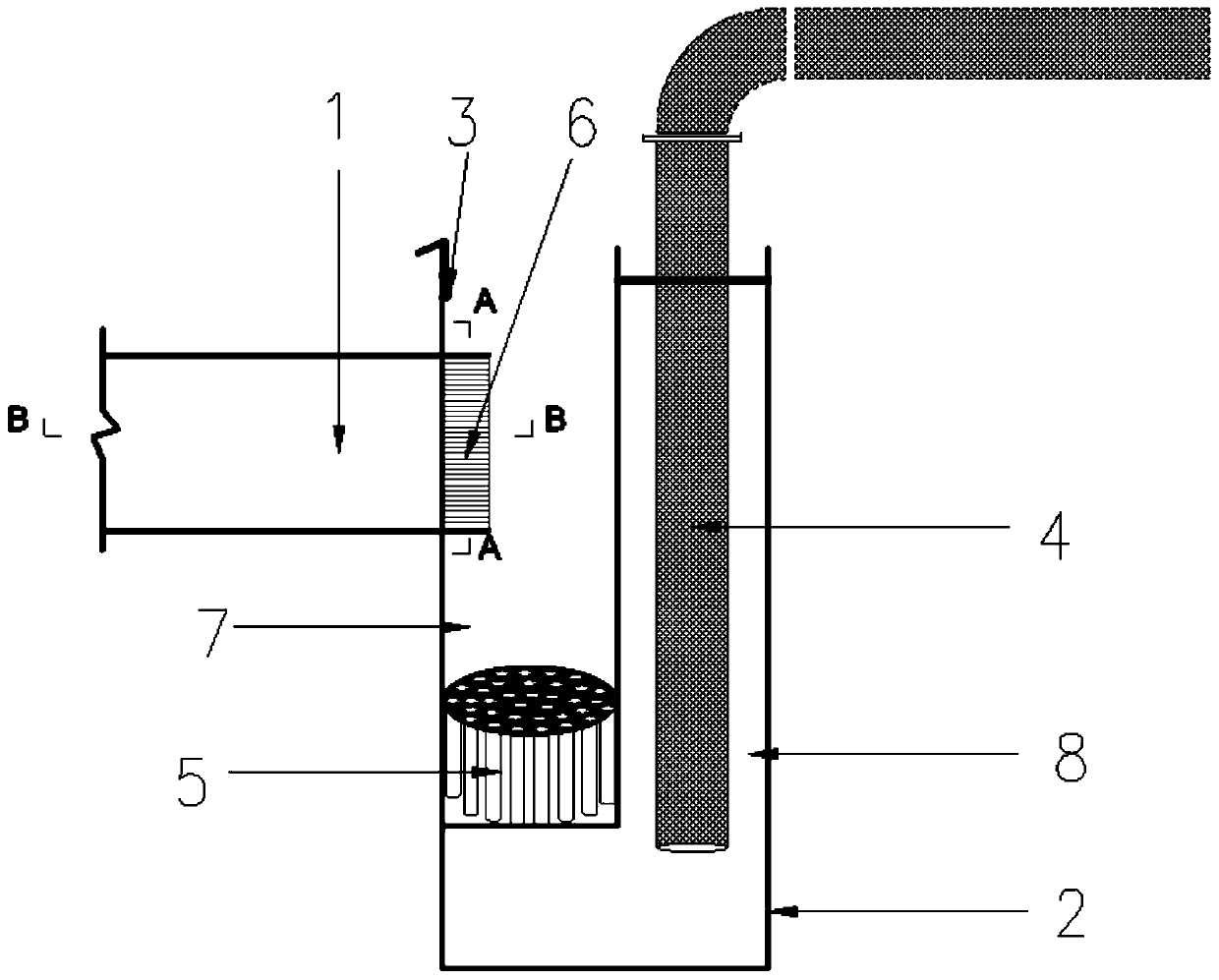
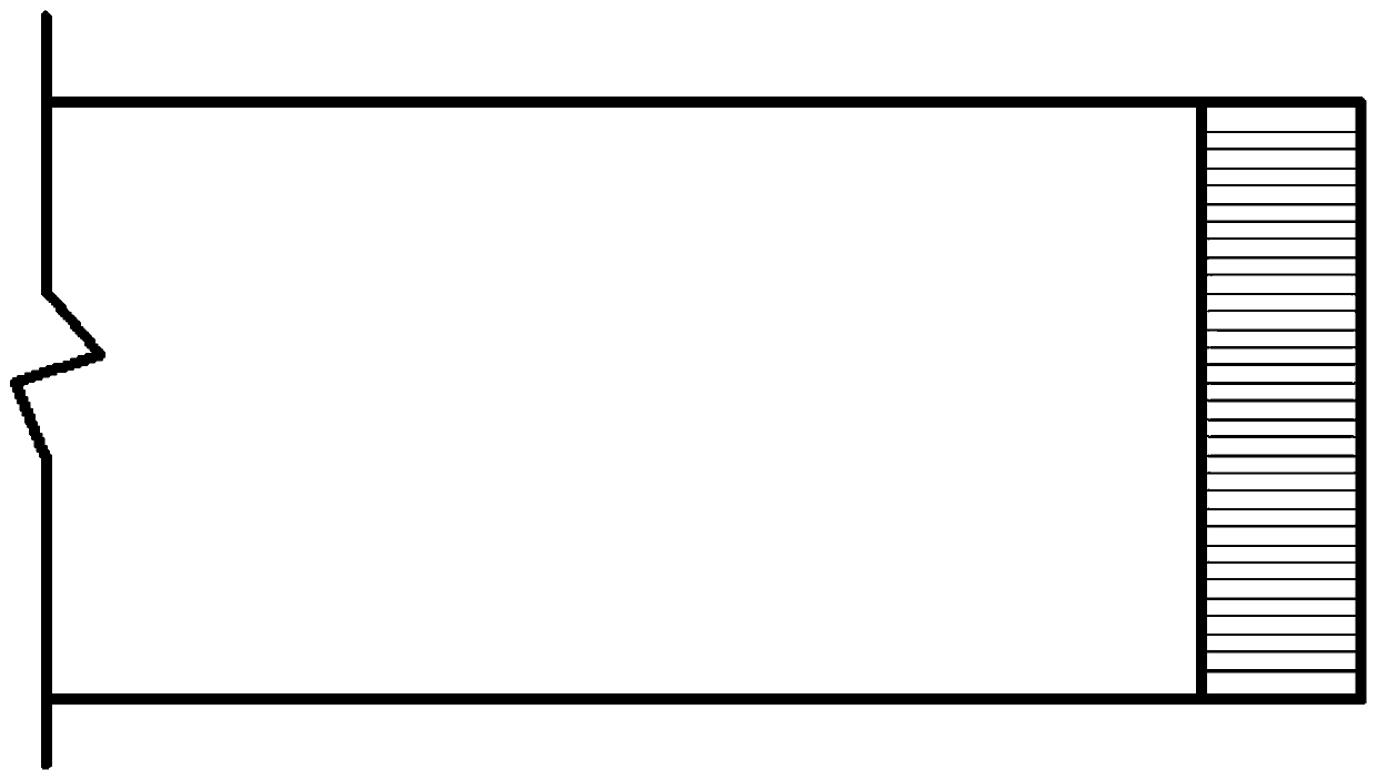
[0034] figure 1 As shown, a water tank 1 water inlet multi-pipe energy dissipation and steady flow system includes a water tank 1, and also includes a rectangular water tank 2 communicated with the water tank 1, image 3 Shown is sink 1 in figure 1 The cross-sectional view of B-B direction in ;

[0035] A partition is installed in the rectangular water tank 2, the partition is L-shaped, the vertical part of the partition is perpendicular to the bottom surface of the rectangular water tank 2, the horizontal part of the partition is parallel to the bottom surface of the rectangular water tank 2, and the horizontal part of the partition is in line with the bottom surface of the rectangular water tank 2. There is a distance between the bottom surfaces of the rectangular water tank 2, and a number of through holes are opened in the horizontal part of the partition. The partition divides the inner cavity of the rectangular water tank 2 into two parts with different volumes, namely ...

Embodiment 2

[0041] Based on the system provided in Example 1, the specific steps for implementation include that the water flow flows into the water supply pipe, flows into the second chamber 8 of the rectangular water tank 2 from the outlet pipe 4 through the connecting elbow, and passes through the through hole in the horizontal part of the partition plate. The water in the second chamber 8 is immersed in the first chamber 7, and as the water flowing into the second chamber 8 gradually increases, the water level in the first chamber 7 gradually rises, and flows steadily through the first multi-water pipe from the bottom The device 5 flows into the water tank 1, while the water flow passes through the second multi-water pipe flow stabilizer 6 when passing through the water inlet of the water tank 1. Through the specific elaboration of the above-mentioned embodiment 1 and embodiment 2, it can be seen that the present application divides and diffuses the water flow provided by the water sup...


PUM


Abstract

The invention relates to a water tank water inlet multi-water-pipe energy dissipation and flow stabilization system and an operation method; the system includes a water tank, and a rectangular water tank that is communicated with the water tank; a partition plate is arranged in the rectangular water tank, and is in a L-shape; the vertical part of the partition plate is vertical to the bottom surface of the rectangular water tank; the horizontal part of the partition plate is parallel to the bottom surface of the rectangular water tank; a distance is reserved between the horizontal part of thepartition plate and the bottom face of the rectangular water tank, the partition plate divides an inner cavity of the rectangular water tank into two parts different in size, a water groove water inlet is formed in the side wall of the rectangular water tank, and a water supply pipeline is arranged above a second cavity of the rectangular water tank and connected with a water outlet pipe which extends into the second cavity. An energy dissipation and flow stabilization body is installed in the first cavity, and the energy dissipation and flow stabilization body comprises a first multi-water-pipe flow stabilizer which is erected in the first cavity; the device can effectively reduce the energy of water flow at a high position before entering the water tank, and the effective length of the experimental section of the working water tank is increased.

Description

technical field [0001] The invention relates to a water tank water inlet multi-pipe energy dissipation and steady flow system and an operation method, belonging to the technical field of experimental infrastructure. Background technique [0002] At present, due to the limited experimental sites in colleges and universities, there is basically no condition to build experimental water tanks with long straight-line distances, especially for water flow research experimental water tanks for teaching. The unstable flow state of the water flow makes the effective working distance of the experimental water tank very limited. In order to improve the use effect of the water tank, necessary flow stabilization treatment must be taken at the water inlet to accommodate the severe water turbulence caused by the difference in water head and excessive instantaneous flow. In other words, it is necessary to take effective measures to eliminate or reduce the turbulent kinetic energy not require...

Claims


Application Information

Patent Timeline
Patent Type & Authority Applications(China)
IPC IPC(8): G09B23/12
CPCG09B23/12
Inventor 秦淑芳严士常曹力玮马洪蛟陈加银张海明于颖
Owner HOHAI UNIV
Why Eureka
Try Eureka