Purge valve noise attenuation system and method

a technology of noise attenuation system and purge valve, which is applied in the direction of fuel injection apparatus, charge feed system, non-fuel substance addition to fuel, etc., can solve the problems of decreasing the likelihood of a vehicle operator hearing noises from the purge valve, unsatisfactory sound waves, etc., to reduce the likelihood of a vehicle operator hearing noises, reduce the turbulent kinetic energy in the gas flow through the diffuser, and reduce the effect of audible noises

Inactive Publication Date: 2015-05-26
FORD GLOBAL TECH LLC
View PDF12 Cites 0 Cited by
  • Summary
  • Abstract
  • Description
  • Claims
  • Application Information

AI Technical Summary

Benefits of technology

[0003]U.S. Pat. No. 6,595,485 discloses a purge valve having a dampening element between a plunger and an outlet tube. The dampening element reduces ticking noise generated during valve operation. Whether or not the purge valve disclosed in U.S. Pat. No. 6,595,485 reduces ticking noises from a purge valve, additional noises may be generated in the valve. Certain flow conditions in the purge valve may generate additional audible noises. For example, high turbulent kinetic energy may be generated in the purge valve during purge operation thereby generating undesirable sound waves which may be heard by the vehicle operator.
[0005]The muffler attenuates noises generated from purge gases traveling through the purge valve, decreasing the likelihood of a vehicle operator hearing noises from the purge valve. Specifically, in some examples, the muffler includes a noise attenuation chamber in fluidic communication with muffling passages opening into a diffuser passage included in the diffuser. As a result, turbulent kinetic energy in the gas flow through the diffuser is reduced, thereby decreasing audible noises generated by the vapor purge valve. Consequently, customer satisfaction may be increased. Furthermore, the configuration of the muffler described above does not significantly increase losses in the purge valve.

Problems solved by technology

For example, high turbulent kinetic energy may be generated in the purge valve during purge operation thereby generating undesirable sound waves which may be heard by the vehicle operator.
The muffler attenuates noises generated from purge gases traveling through the purge valve, decreasing the likelihood of a vehicle operator hearing noises from the purge valve.

Method used


Image

  • Purge valve noise attenuation system and method
  • Purge valve noise attenuation system and method
  • Purge valve noise attenuation system and method

Examples


Embodiment Construction

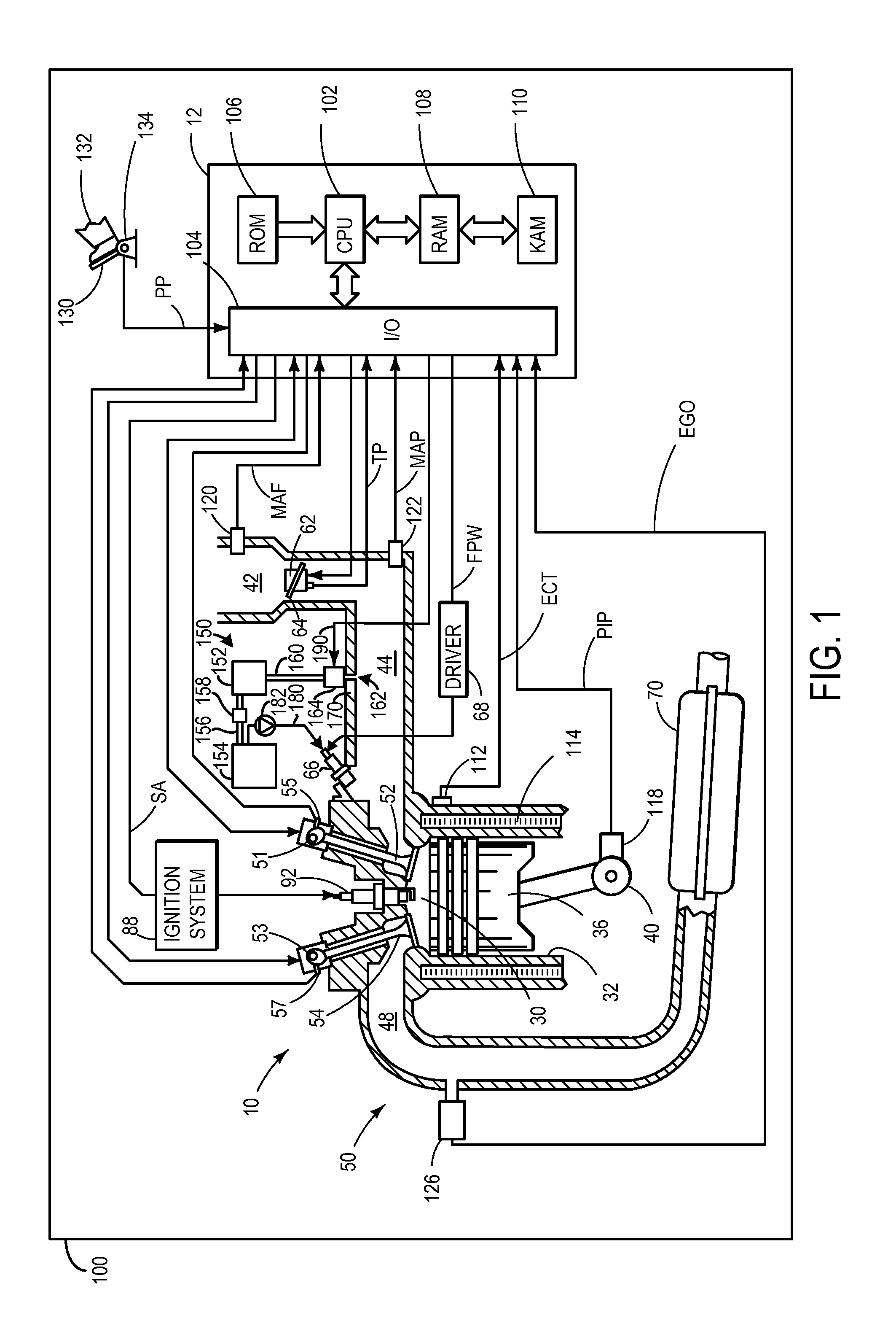
[0014]The following description relates to an approach for reducing noise generation in a vapor purge valve. The purge valve may include a muffler. The muffler may include a noise attenuation chamber and muffling passages enabling fluidic communication between a diffuser included in the muffler and the chamber. The muffling passages and the noise attenuation chamber enable turbulent kinetic energy in the gas flow through the diffuser to be reduced, thereby decreasing audible noise generated by the vapor purge valve. Consequently, customer satisfaction may be increased.

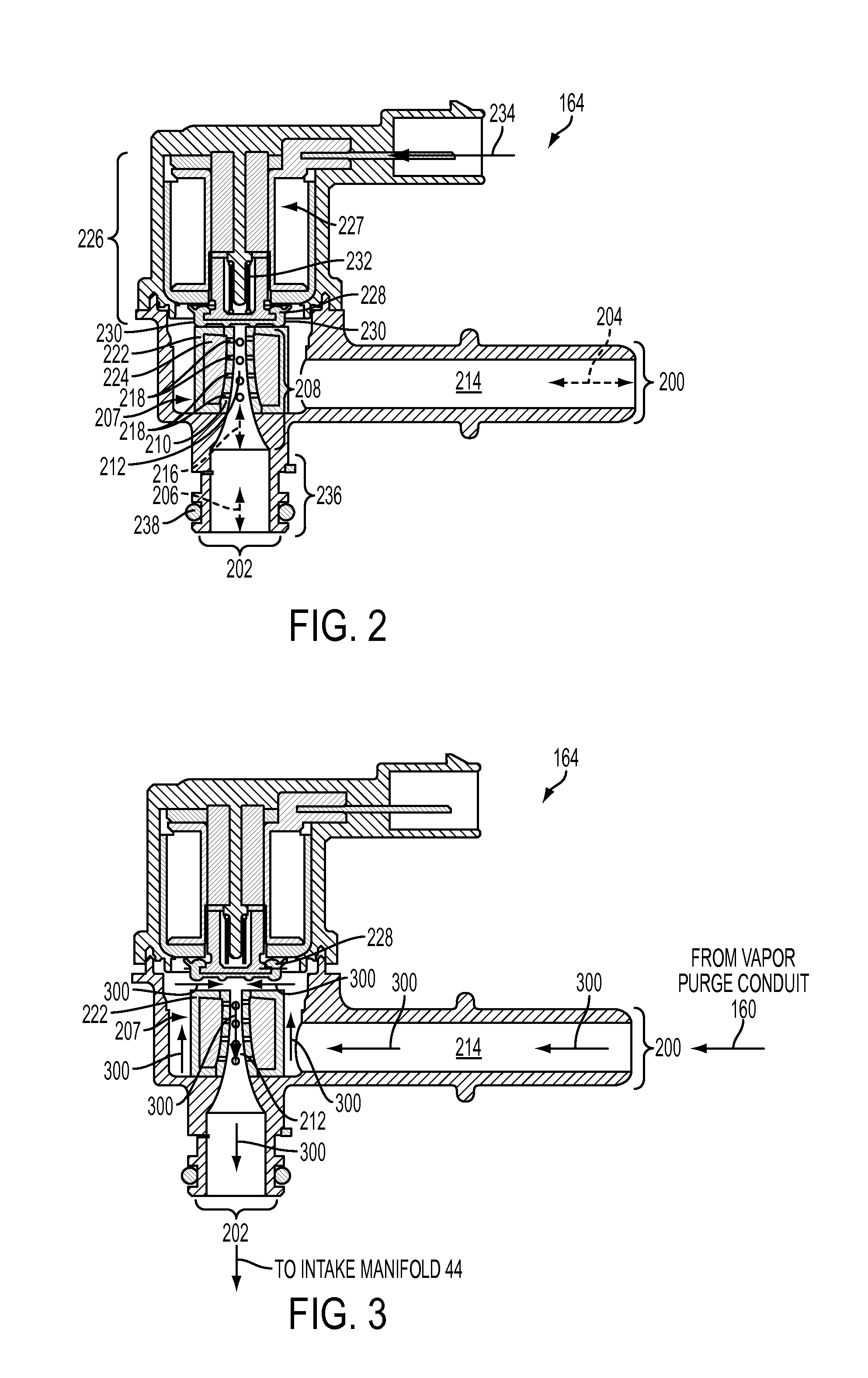
[0015]FIG. 1 shows a schematic depiction of an engine including a vapor purge system having a vapor purge valve. FIG. 2 shows an illustration of an example vapor purge valve. FIG. 3 shows the general direction of purge gas flow in the vapor purge valve shown in FIG. 2 during purge operation. FIG. 4 shows a detail illustration of an example diffuser and muffler included in the vapor purge valve shown in FIG. 2. FIG. 5 s...


PUM


Abstract

A vapor purge valve in an engine is provided. The vapor purge valve includes a purge valve inlet, a purge valve outlet, and a muffler including a housing at least partially enclosing a diffuser in fluidic communication with the purge valve inlet and the purge valve outlet.

Description

FIELD[0001]The present disclosure relates to a vapor purge system including a vapor purge valve dampening noise generated in the valve.BACKGROUND AND SUMMARY[0002]Vapor purge systems are used in engines to decrease emissions. Vapor purge systems may include a vapor purge canister in fluidic communication with an intake passage. Fuel vapor may build up in the purge canister during engine operation. A vapor purge valve may be used to implement purge operation and control transfer of fuel vapors from the purge canister to the intake manifold at desired operating conditions.[0003]U.S. Pat. No. 6,595,485 discloses a purge valve having a dampening element between a plunger and an outlet tube. The dampening element reduces ticking noise generated during valve operation. Whether or not the purge valve disclosed in U.S. Pat. No. 6,595,485 reduces ticking noises from a purge valve, additional noises may be generated in the valve. Certain flow conditions in the purge valve may generate additio...

Claims


Application Information

Patent Timeline
Patent Type & Authority Patents(United States)
IPC IPC(8): F02M25/08F02M33/02
CPCF02M25/08F02M25/0836F02M25/0872F02M2025/0845
Inventor KARIM, AHSANULZOUANI, ABDELKRIMPLYMALE, KEVIN WILLIAMZENG, PAUL
Owner FORD GLOBAL TECH LLC
Why Eureka
Try Eureka