How the robot is made

A manufacturing method and robot technology, applied in manufacturing tools, assembly machines, manipulators, etc., can solve the problems of operator convenience, low operation safety, long assembly time, and inability to assemble, so as to shorten assembly operation time, reduce The effect of waiting time and improving safety

Active Publication Date: 2021-11-12
NIDEC SANKYO (ZHEJIANG) CORPORATION +1
View PDF5 Cites 0 Cited by
  • Summary
  • Abstract
  • Description
  • Claims
  • Application Information

AI Technical Summary

Problems solved by technology

[0006] Like this, when making above-mentioned robot in the past, be to assemble from bottom to top mode, therefore can't to each unit such as the base unit of robot, column unit, assemble simultaneously, and the parts and components of robot are numerous (may reach thousands of parts) ), resulting in long assembly time and inefficient assembly work
[0007] In addition, in recent years, liquid crystal panels have become larger and larger, and correspondingly, the above-mentioned robots have also become larger. Sometimes, the elongated column main body included in the column unit may reach a length of more than 10 meters.
[0008] Under the above circumstances, when assembling the arm unit and the hand unit (mainly assembling the functional components included in the arm unit and the hand unit) on the main body of the column, it is often necessary to carry out high-altitude operations for a long time, which is dangerous and greatly improves the convenience of the operator. , The safety of the operation is also low, and it is not easy to reliably ensure the assembly accuracy of the assembled robot, which may easily lead to problems such as poor performance and loss of function of the robot.

Method used


Image

  • How the robot is made
  • How the robot is made
  • How the robot is made

Examples


Embodiment Construction

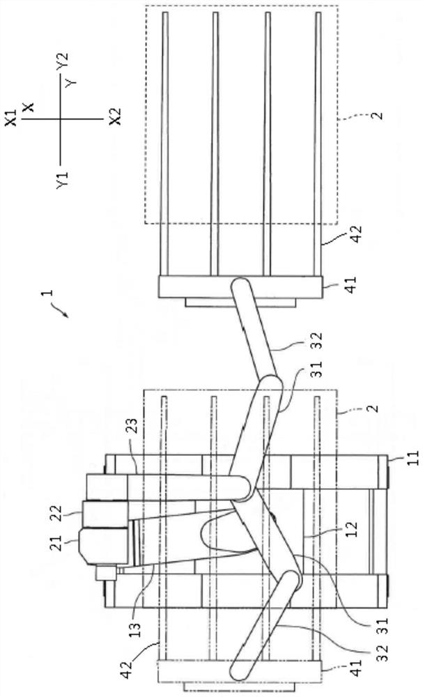
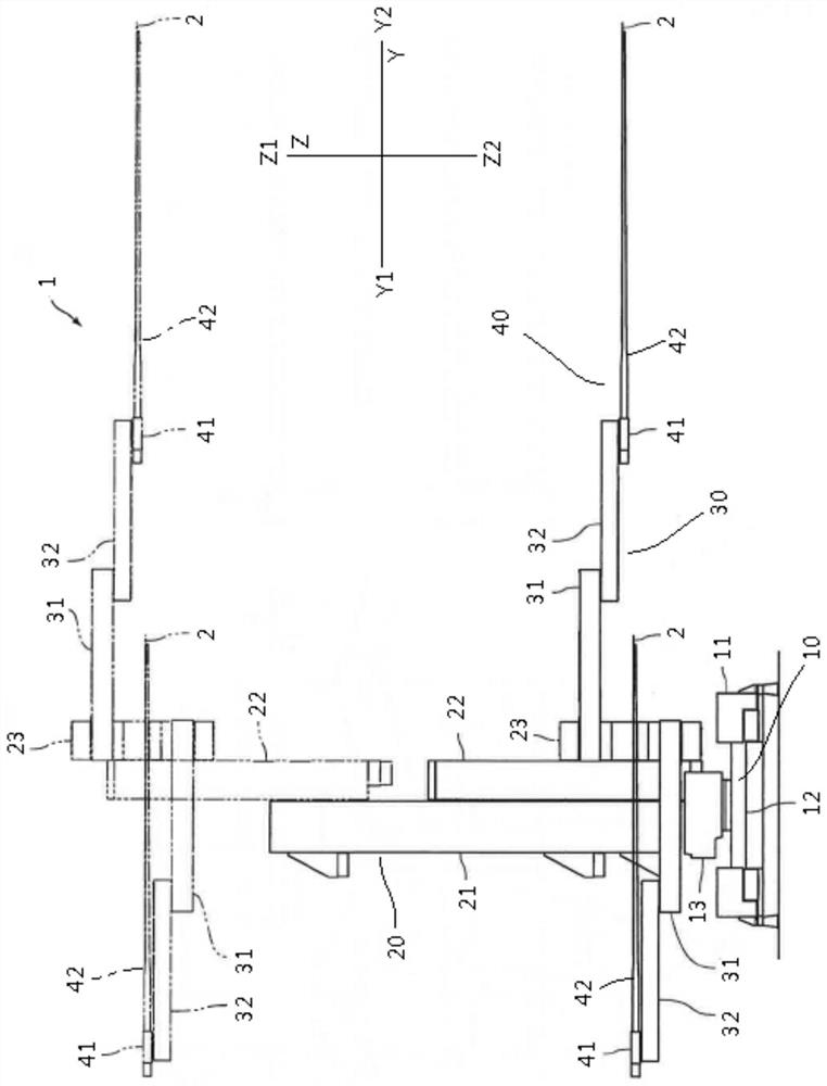
[0054] Below, refer to figure 1 and figure 2 , to describe the embodiment of the present invention, wherein, figure 1 It is a top view schematically showing the robot according to the embodiment of the present invention, and the solid line indicates the state in which the hand unit is stretched out, and the dotted line indicates the state in which the hand unit is retracted, figure 2 yes figure 1 The side view of the robot is shown, and the solid line indicates the state of the hand unit in the lowered position, and the dashed line indicates the state of the hand unit in the raised position.

[0055] In addition, for the convenience of description, let the three directions orthogonal to each other be the X direction, the Y direction and the Z direction, and let one side of the X direction be X1, let the other side of the X direction be X2, and let the Y One side of the direction is Y1, the other side of the Y direction is Y2, one side of the Z direction is Z1, and the oth...


PUM


Abstract

A manufacturing method of a robot helps to improve the efficiency and safety of the manufacturing operation of the robot. In the manufacturing method of the robot of the present invention, the robot includes: a base unit; a column unit vertically supported on the base unit; an arm unit connected to the column unit in a rotatable manner; and a hand A unit in which the hand unit is rotatably connected to the arm unit includes: a unit assembling step in which base unit assembling work, column unit assembling work, arm unit assembling work, and hand unit assembling work are performed , at least two of the base unit assembly work, the column unit assembly work, the arm unit assembly work, and the hand unit assembly work are performed in parallel; and a complete machine assembly step in which the unit assembly The base unit, column unit, arm unit, and hand unit assembled in the steps are connected together.

Description

technical field [0001] The invention relates to a method for manufacturing a robot. Background technique [0002] In order to improve production efficiency, reduce labor costs, and improve the safety of operations, robots are currently used in many industries. [0003] For example, in the production line of liquid crystal panels, robots are often used to carry out operations such as handling of liquid crystal panels. [0004] A robot used on a production line of liquid crystal panels generally includes: a base unit; a column unit supported on the base unit in an upright manner; an arm unit connected to the column unit in a rotatable manner and a hand unit which is rotatably connected to the arm unit. [0005] In the past, when manufacturing the above-mentioned robot, the base unit is usually assembled first, then the elongated column main body included in the column unit is erected on the base unit, and then guide rails, driving parts, cables, etc. are installed on the col...

Claims


Application Information

Patent Timeline
Patent Type & Authority Patents(China)
IPC IPC(8): B25J19/00B23P21/00
CPCB23P21/00B25J19/007
Inventor 王卿今井英幸
Owner NIDEC SANKYO (ZHEJIANG) CORPORATION
Why Eureka
Try Eureka