
Die system for manufacturing track beam

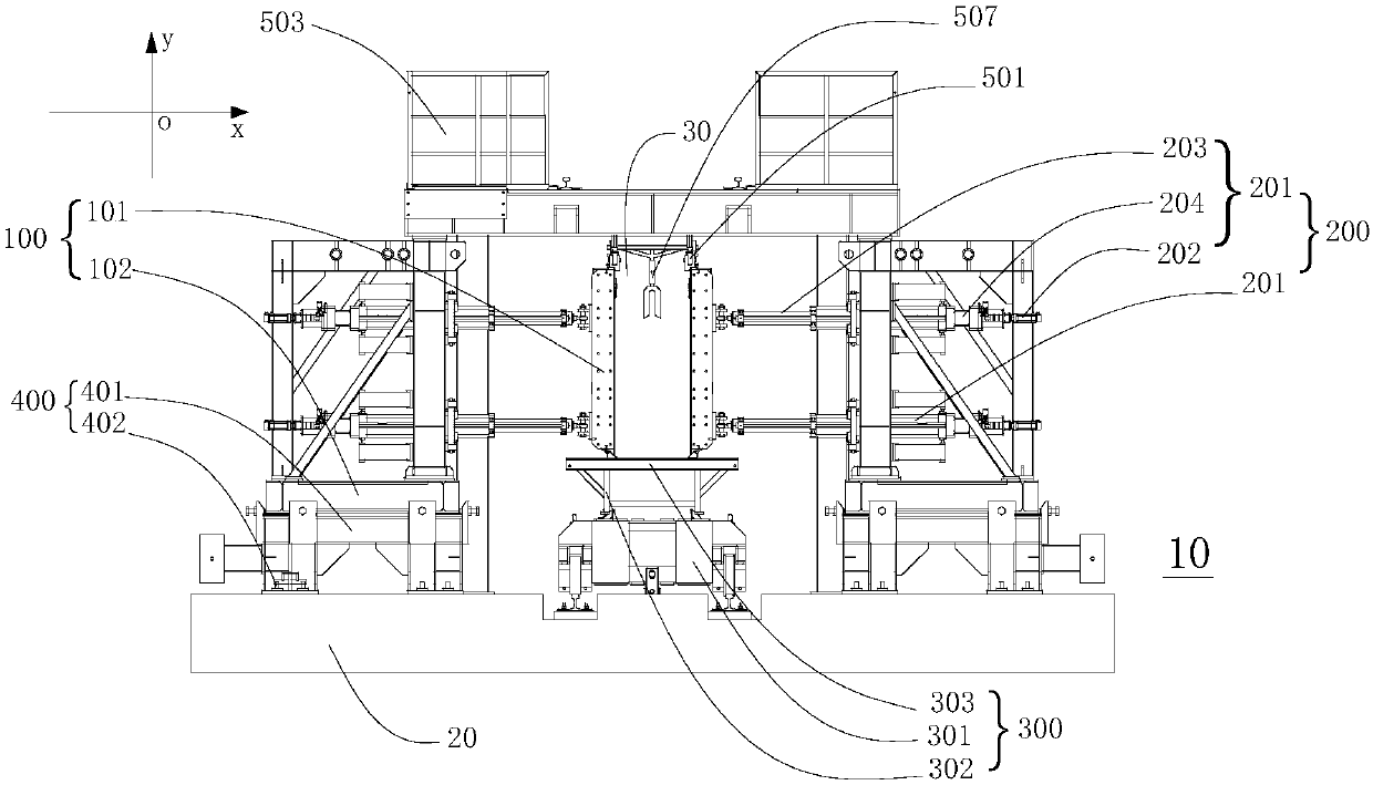
A technology of track beams and molds, which is applied in the field of rail transit, can solve problems such as the inability to carry out overall relocation, and achieve the effects of stable and reliable structure, cost saving, and high degree of automation

Inactive Publication Date: 2020-06-23
BYD CO LTD
View PDF5 Cites 0 Cited by
  • Summary
  • Abstract
  • Description
  • Claims
  • Application Information

AI Technical Summary

Problems solved by technology

[0002] In the existing technology, in the manufacture of track beams, traditional manual feeding operations are required one by one, and the degree of bending of the formwork needs to be observed from time to time during the operation
In addition, the side formwork system and the side formwork steel frame system need to be installed and debugged on site. During the next track beam manufacturing, the formwork and steel frame must be disassembled and transported to the next construction site, and the overall relocation cannot be carried out.

Method used


Image

  • Die system for manufacturing track beam
  • Die system for manufacturing track beam
  • Die system for manufacturing track beam

Examples


Embodiment Construction

[0047] In order to make the technical problems, technical solutions and beneficial effects solved by the present invention clearer, the present invention will be further described in detail below in conjunction with the accompanying drawings and embodiments. It should be understood that the specific embodiments described here are only used to explain the present invention, not to limit the present invention.

[0048] Embodiments of the present invention are described in detail below, examples of which are shown in the drawings, wherein the same or similar reference numerals designate the same or similar elements or elements having the same or similar functions throughout. The embodiments described below by referring to the figures are exemplary only for explaining the present invention and should not be construed as limiting the present invention.

[0049]In describing the present invention, it is to be understood that the terms "center", "longitudinal", "transverse", "vertica...


PUM


Abstract

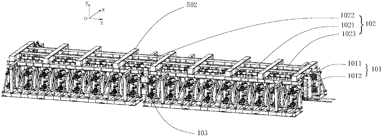
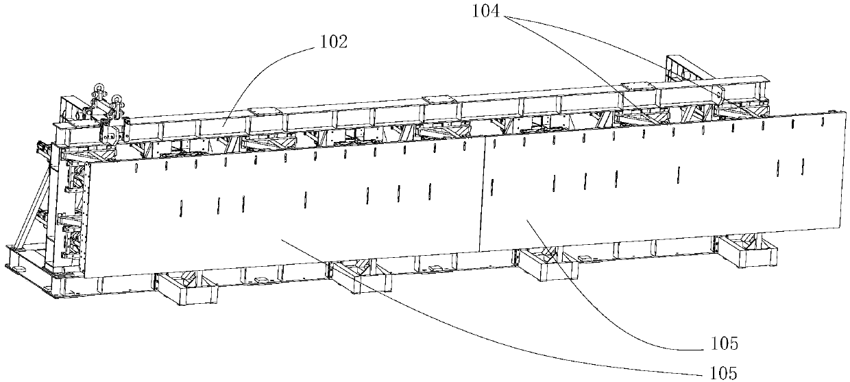
The invention provides a die system for manufacturing a track beam. The die system for manufacturing the track beam involves side die devices and a driving device, wherein the side die devices are arranged on the two sides of the die system in the width direction and extend in the length direction of the die system; the side die devices comprise side formwork assemblies, the side formwork assemblies comprises side formworks, and the side formworks can be bent and are suitable for making contact with the track beam so that the track beam can be formed; and the driving device comprises a plurality of driving assemblies, and at least two driving assemblies are connected with the side formworks so as to drive the corresponding side formworks to move or bend. According to the die system for manufacturing the track beam, automation of manufacturing of a straight beam and a curved beam of the track beam can be achieved, and overall moving can be achieved.

Description

technical field [0001] The invention relates to the technical field of rail transportation, in particular to a mold system for manufacturing rail beams. Background technique [0002] In the existing technology, in the manufacture of track beams, traditional manual feeding operations are required one by one, and the degree of bending of the formwork needs to be observed from time to time during the operation. In addition, the side formwork system and the side formwork steel frame system need to be installed and debugged on site. During the next track beam manufacturing, the formwork and steel frame must be disassembled and transported to the next construction site, and the overall relocation cannot be carried out. Contents of the invention [0003] The present invention aims to solve at least one of the technical problems existing in the prior art. Therefore, the present invention proposes a rail beam mold system, which can realize the automation of manufacturing straight ...

Claims


Application Information

Patent Timeline
Patent Type & Authority Applications(China)
IPC IPC(8): B28B21/82
CPCB28B21/82
Inventor 王传方邵淦储昭节杜金源
Owner BYD CO LTD
Learn More