Thermal management system and new energy automobile

A thermal management system and thermal management technology, applied in the field of thermal management systems and new energy vehicles, can solve problems such as the inability to control the temperature of the coolant and the inability to guarantee the temperature control of the second thermal management object

Active Publication Date: 2020-06-23
HUAWEI DIGITAL POWER TECH CO LTD
View PDF7 Cites 6 Cited by
  • Summary
  • Abstract
  • Description
  • Claims
  • Application Information

AI Technical Summary

Problems solved by technology

In the case of serial connection, since the temperature of the cooling liquid flowing through the first thermal management object changes, when the temperature-changed cooling liquid flows to

Method used


Image

  • Thermal management system and new energy automobile
  • Thermal management system and new energy automobile
  • Thermal management system and new energy automobile

Examples


Embodiment 1

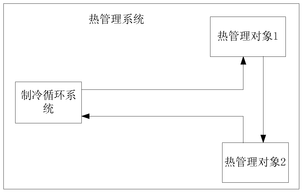
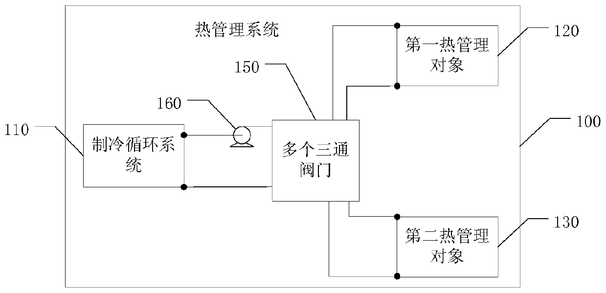
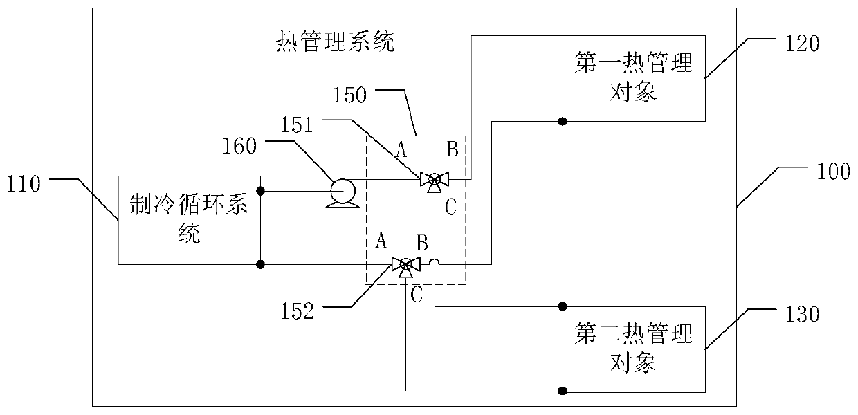
[0055] Such as diagram 2-1 As shown, the embodiment of the present application proposes a thermal management system 100, the thermal management system 100 includes a refrigeration cycle system 110, a flow path pump 160, a first thermal management object 120, a second thermal management object 130 and a plurality of three-way Valve 150. Among them, the refrigeration cycle system 110 and the flow path pump 160 are respectively connected to a plurality of three-way valves 150, and the refrigeration cycle system 110 and the flow path pump 160 are respectively connected to the first heat management object 120 and the second heat management object through a plurality of three-way valves 150. 130, thereby forming a first coolant circulation loop and a second coolant circulation loop independent of each other.

[0056] Wherein, the refrigeration cycle system 110 is used to control the temperature of the cooling liquid. The flow path pump 160 is used to pressurize the coolant so tha...

Embodiment 2

[0092] Such as Figure 10-1 As shown, the embodiment of the present application also provides a thermal management system 200. The thermal management system 200 includes two sets of thermal management subsystems, one for cooling and the other for heating.

[0093] Specifically, the refrigeration subsystem includes: a cooler 211 in the refrigeration cycle system 210, a first flow path pump 261, a cold core 221 in the HVAC system 220, a battery pack 230, a first temperature compensation pump 241, and a first three-way valve 251 and the second three-way valve 252. Wherein, the cooler 211 is connected to the first flow path pump 261, the cooler 211 and the first flow path pump 261 are respectively connected to the first three-way valve 251 and the second three-way valve 252, and the first three-way valve 251 is respectively connected to the cold core 221 and the battery The battery pack 230 and the second three-way valve 252 are respectively connected to the cold core 221 and the...


PUM


Abstract

The embodiment of the invention discloses a thermal management system and a new energy automobile. The thermal management system includes a refrigeration circulating system, a flow path pump, a firstthermal management object, a second thermal management object, and a plurality of three-way valves; the refrigeration circulating system and the flow path pump are connected with the plurality of three-way valves; the refrigeration circulating system and the flow path pump are respectively connected with the first heat management object and the second heat management object through the plurality of three-way valves; through the independent control of each three-way valve in the plurality of three-way valves, a first cooling liquid circulation loop and a second cooling liquid circulation loop which are independent of each other are formed, so that independent temperature control of the first heat management object and the second heat management object is realized. The new energy automobilecomprises a motor and the thermal management device.

Description

technical field [0001] This application relates to the field of thermal management, in particular to a thermal management system and new energy vehicles. Background technique [0002] Electric vehicles mainly provide energy through batteries. Compared with traditional fuel vehicles, batteries have the characteristics of energy saving and environmental protection. Generally, the best operating temperature range of the battery is 20°C to 45°C, too high or too low temperature will have a negative impact on the performance and life of the battery. Therefore, in practical application scenarios, thermal management of the battery is required. [0003] For the thermal management of the battery, it is currently mainly carried out through indirect heat exchange. Indirect heat exchange refers to a form of heat exchange in which heat exchange media do not directly contact each other. It is a heat exchange form with low production cost and high production efficiency in terms of time an...

Claims


Application Information

Patent Timeline
IPC IPC(8): B60L58/26B60H1/00
CPCB60L58/26B60H1/00278B60H1/00392B60L2240/545B60H2001/00307Y02T10/70B60H1/32284Y02E60/10B60H1/00885B60L2240/36B60L2240/425B60L58/27B60L2240/525B60H1/00485H01M10/613H01M10/625H01M10/6568H01M10/663H01M2220/20
Inventor 陈君刘超鹏
Owner HUAWEI DIGITAL POWER TECH CO LTD
Why Eureka
Try Eureka