Textile machinery conveying chain mechanism capable of being continuously used and free of replacement in case of small part damage

A textile machinery, replacement-free technology, applied in the field of textile machinery transmission, can solve the problems of poor durability of the conveyor chain, damage to the conveyor chain, poor protection effect of the conveyor chain, etc. effect of probability

Active Publication Date: 2020-06-23
周国仙
View PDF11 Cites 1 Cited by
  • Summary
  • Abstract
  • Description
  • Claims
  • Application Information

AI Technical Summary

Problems solved by technology

[0003] In order to solve the above-mentioned technical problems, the present invention provides a textile machinery conveyor chain mechanism that does not need to be replaced if the small part is damaged, so as to solve the problem that the existing similar textile machinery conveyor chain mechanism has poor protection effect on the conveyor chain itself when it is in use, and the transmission The chain drive is easily affected by various external factors during operation, resulting in damage to some parts of the conveyor chain, and the durability of the conveyor chain is poor. When some parts of the conveyor chain are damaged, it cannot continue to be used. The replacement of the conveyor chain will easily affect the running effect of the textile machinery

Method used


Image

  • Textile machinery conveying chain mechanism capable of being continuously used and free of replacement in case of small part damage
  • Textile machinery conveying chain mechanism capable of being continuously used and free of replacement in case of small part damage
  • Textile machinery conveying chain mechanism capable of being continuously used and free of replacement in case of small part damage

Examples


Embodiment

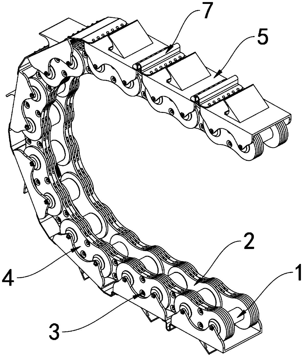
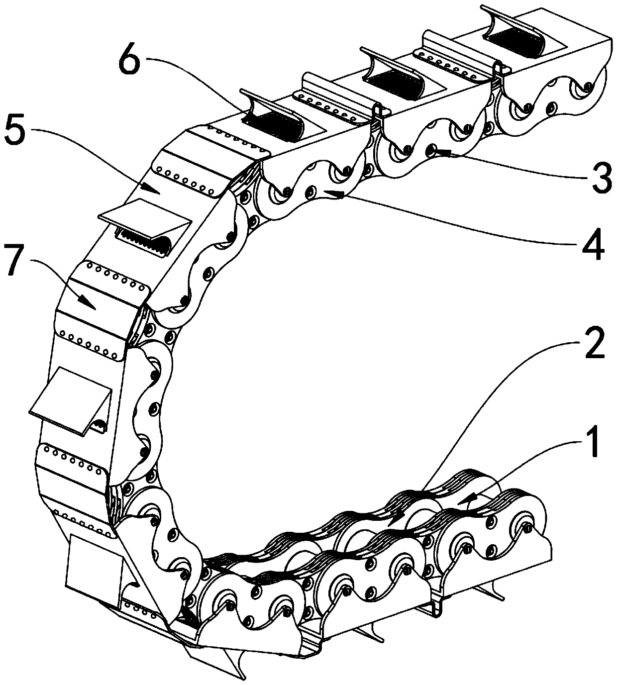
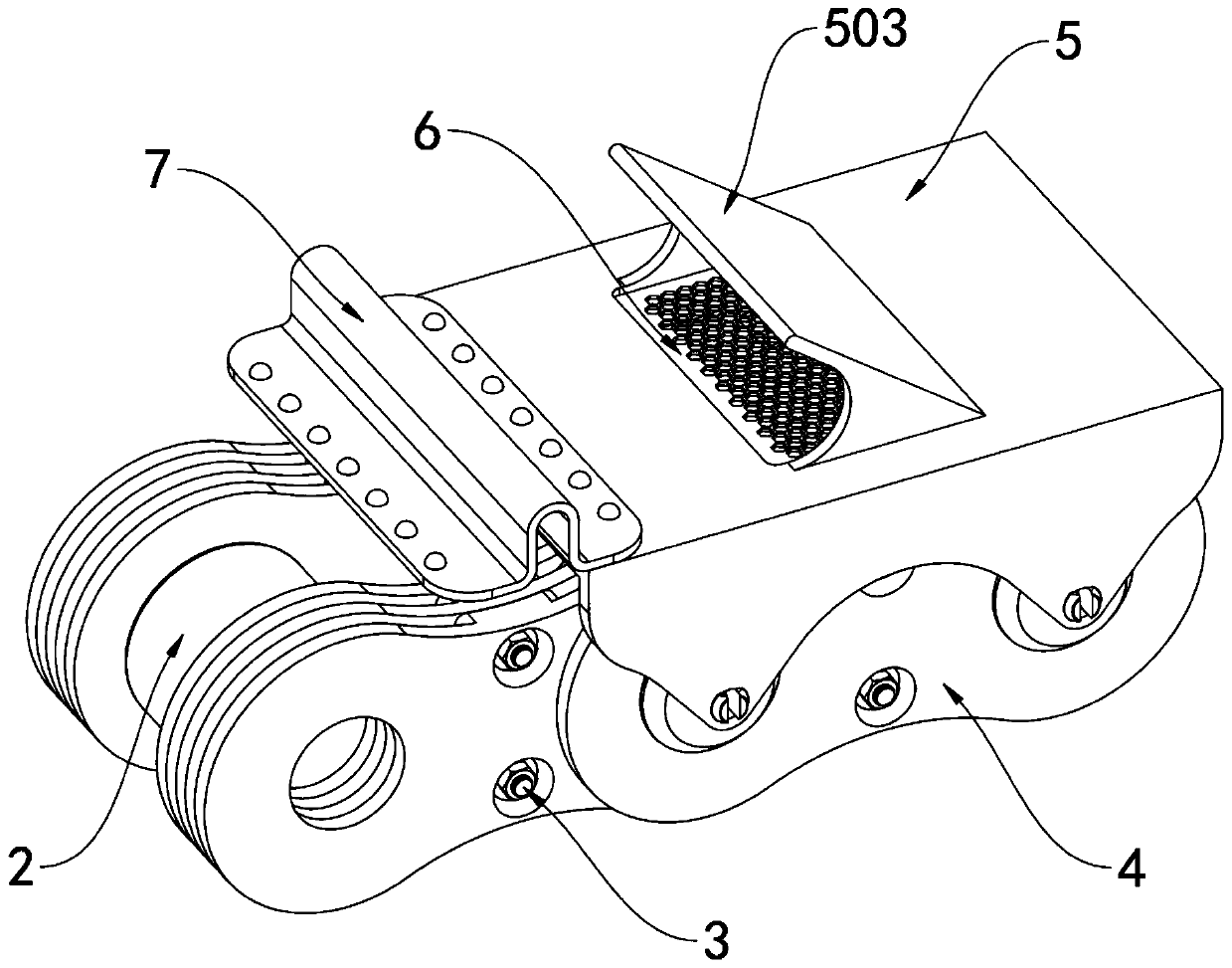
[0031] as attached figure 1 to attach Figure 9 Shown:

[0032] The present invention provides a textile machinery conveying chain mechanism that can be used without replacement if small parts are damaged. Chain condition 1 and No. 2 chain condition 2 share multiple places, and No. 1 chain condition 1 is respectively connected to two No. 2 chain conditions 2, and the No. 1 chain condition 1 and No. 1 chain condition 1 pass through No. 2 chain condition 2 are connected; the bolts 3 are respectively located on the left and right sides of the first chain condition 1 and the left and right sides of the second chain condition 2; There are two assembly holes 401; the protective shell 5 is located at the top of the No. 1 chain condition 1, and the filter plate 6 is installed in the top of the protective shell 5; There is an air guide inclined plate 503 on the top, and the air guide inclined plate 503 is located at the top of the air intake radiating port 501. When the No. 1 chain ...


PUM


Abstract

The invention provides a textile machinery conveying chain mechanism capable of being continuously used and free of replacement in case of small part damage, and relates to the technical field of textile machinery transmission. The textile machinery conveying chain mechanism comprises first chain parts and second chain parts, the first chain parts and second chain parts are multiple in number, thefirst chain parts are rotationally connected with the two second chain parts correspondingly, and the first chain parts are connected with the first chain parts through the second chain parts; boltsare located on the left and right sides of the first chain parts and the left and right sides of the second chain parts correspondingly, a plurality of auxiliary chain plates are arranged, every two auxiliary chain plates form a group, and two assembly holes are formed inside each auxiliary chain plate, a protective shell is located at the tops of the first chain parts, and a filter screen plate is installed in the top of the protective shell. According to the textile machinery conveying chain mechanism, the outer sides of the first chain parts and the second chain parts are protected throughthe auxiliary chain plates, when the auxiliary chain plates on the outer sides of the first chain parts and the second chain parts are damaged due to poor protection, the first chain parts and the second chain parts can still continue to conduct transmission operation, and therefore the damage replacement probability of the conveying chain is reduced.

Description

technical field [0001] The invention belongs to the technical field of textile machinery transmission, and more specifically relates to a textile machinery conveying chain mechanism that can be used without replacement if a small part is damaged. Background technique [0002] With the development of the textile industry and the increase in people's demand for fabrics, the production efficiency of textile machinery has also been improved more and more. During the operation and processing of textile machinery, conveyor chains are usually used for transmission operation. Conveyor chains are used as very Important transmission components are widely used in various types of textile machinery; the conveyor chain mechanism for textile machinery can refer to the CN105366279B patent, which mainly includes that the outer curved plate is installed on the head of the pin shaft and rests on the steps of the pin shaft, The shaft sleeve is installed on the pin shaft and its left end face i...

Claims


Application Information

Patent Timeline
Patent Type & Authority Applications(China)
IPC IPC(8): B65G17/40
CPCB65G17/40B65G2207/22
Inventor 屈珠丽
Owner 周国仙
Why Eureka
Try Eureka